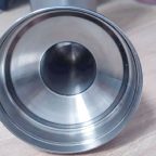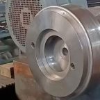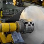
Sheet metal spinning is a versatile manufacturing process used to produce axisymmetric components by rotating a metal blank and applying localized pressure with a tool to form the material over a mandrel or freeform shape. Multi-pass sheet metal spinning, in particular, involves multiple forming stages to achieve complex geometries with enhanced precision and material properties. Numerical modelling, validation, and analysis of multi-pass sheet metal spinning processes have become critical in modern manufacturing to optimize process parameters, predict defects, and ensure product quality. This article provides a comprehensive exploration of the theoretical foundations, numerical techniques, validation methodologies, and analytical approaches associated with multi-pass sheet metal spinning, emphasizing finite element analysis (FEA), experimental validation, and comparative studies.
Introduction to Sheet Metal Spinning
Sheet metal spinning, also known as spin forming or metal spinning, is a cold-forming process that transforms a flat metal blank into a hollow, axisymmetric part through localized plastic deformation. The process typically involves clamping a metal blank against a rotating mandrel and using a roller or tool to incrementally deform the material. Multi-pass spinning extends this technique by employing multiple forming stages, each with specific tool paths, to achieve complex shapes, improve dimensional accuracy, and control material thinning. This process is widely used in industries such as aerospace, automotive, and energy for manufacturing components like turbine casings, pressure vessels, and automotive wheels.
Numerical modelling of multi-pass spinning enables engineers to simulate the process, predict material behavior, and optimize parameters such as tool path, feed rate, and spindle speed. Validation ensures that these models accurately represent real-world conditions, while analysis provides insights into stress distribution, strain evolution, and defect formation. This article delves into the intricacies of these aspects, drawing on theoretical, computational, and experimental perspectives.
Fundamentals of Multi-Pass Sheet Metal Spinning
Process Mechanics
In multi-pass sheet metal spinning, the metal blank is subjected to a series of incremental deformations. Each pass involves a specific tool trajectory, typically defined by a roller moving along a predetermined path. The process can be categorized into conventional spinning, shear spinning, and flow forming, depending on the deformation mode and thickness reduction. Multi-pass spinning is particularly suited for conventional spinning, where the blank is formed over a mandrel without significant thickness reduction.
The mechanics of multi-pass spinning involve complex interactions between the tool, blank, and mandrel. The roller applies localized pressure, inducing plastic deformation in the contact zone. This deformation propagates through the blank, causing bending, stretching, and shearing. The multi-pass approach allows for gradual shape evolution, reducing the risk of defects such as wrinkling, cracking, or excessive thinning.
Material Behavior
The material properties of the blank significantly influence the spinning process. Common materials include aluminum alloys, stainless steel, titanium, and high-strength steels, each exhibiting distinct flow characteristics, work hardening, and anisotropy. The material’s constitutive behavior is typically modeled using plasticity theories, such as von Mises or Hill’s yield criteria, to account for isotropic or anisotropic properties, respectively.
During multi-pass spinning, the material undergoes cyclic loading, leading to strain hardening and potential Bauschinger effects. The accumulation of plastic strain across passes affects the material’s flow stress, necessitating accurate material models in numerical simulations. Temperature effects, although minimal in cold forming, may arise due to frictional heating, particularly in high-speed spinning.
Process Parameters
Key process parameters in multi-pass spinning include:
- Spindle Speed: The rotational speed of the mandrel, typically ranging from 100 to 1000 RPM, affects frictional heating and material flow.
- Feed Rate: The axial or radial speed of the roller, usually 0.5–5 mm/rev, influences deformation rate and surface finish.
- Tool Path: The trajectory of the roller, which may involve linear, curved, or spline-based paths, determines the shape evolution.
- Roller Geometry: The radius and profile of the roller affect contact pressure and deformation zone size.
- Lubrication: The type and application of lubricant reduce friction and wear, impacting surface quality and tool life.
These parameters are optimized through numerical modelling to achieve desired outcomes, such as uniform thickness distribution and minimal residual stresses.
Numerical Modelling of Multi-Pass Sheet Metal Spinning
Numerical modelling, particularly finite element analysis (FEA), is a cornerstone of modern process simulation in multi-pass sheet metal spinning. FEA enables the prediction of stress, strain, and displacement fields, facilitating process optimization and defect prevention.
Finite Element Method (FEM) Framework
The FEM framework for multi-pass spinning involves discretizing the blank, mandrel, and roller into finite elements, typically 3D solid or shell elements. The governing equations are based on continuum mechanics, incorporating equilibrium, compatibility, and constitutive relations. The general steps in FEM simulation include:
- Geometry and Mesh Generation: The blank is modeled as a deformable body, while the mandrel and roller are often treated as rigid surfaces. A fine mesh is used in the deformation zone to capture localized effects, with adaptive meshing to handle large deformations.
- Material Model: A constitutive model, such as an elastoplastic model with isotropic or kinematic hardening, describes the material’s response. For anisotropic materials, Hill’s 1948 yield criterion or more advanced models like Barlat’s are employed.
- Boundary Conditions: The blank is clamped at its periphery, and the mandrel rotates at a specified speed. The roller follows a prescribed tool path, applying contact pressure.
- Contact and Friction: A Coulomb friction model or shear friction model is used to simulate interactions between the blank, mandrel, and roller. Friction coefficients typically range from 0.05 to 0.2, depending on lubrication.
- Solution Scheme: Explicit or implicit time integration schemes are used to solve the dynamic or quasi-static problem. Explicit schemes are preferred for high-speed processes, while implicit schemes offer stability for complex geometries.
Modelling Multi-Pass Strategies
Multi-pass spinning requires modelling sequential forming stages, each with distinct tool paths. The simulation must account for the cumulative effects of prior passes, including residual stresses and strain hardening. Two approaches are commonly used:
- Sequential Simulation: Each pass is simulated consecutively, with the deformed geometry and material state from one pass serving as the initial condition for the next. This approach is computationally intensive but accurate.
- Simplified Multi-Pass Models: Approximate methods, such as mapping the cumulative strain from a single-pass model, are used for rapid analysis. These are less accurate but suitable for preliminary design.
Software Tools
Several commercial and open-source FEA software packages are used for spinning simulations, including:
- ABAQUS: Widely used for its robust explicit and implicit solvers, suitable for complex contact problems.
- ANSYS: Offers advanced material models and adaptive meshing for spinning simulations.
- LS-DYNA: Preferred for explicit dynamic simulations, particularly for high-speed spinning.
- Marc: Known for its nonlinear capabilities and suitability for metal forming.
- OpenFOAM: An open-source alternative for custom simulations, though less common in spinning.
Each software has strengths and limitations, as summarized in the following table:
| Software | Strengths | Limitations | Typical Use Case |
|---|---|---|---|
| ABAQUS | Robust contact algorithms, versatile material models | High computational cost for explicit simulations | Complex multi-pass simulations |
| ANSYS | User-friendly interface, adaptive meshing | Limited explicit solver performance | General spinning analysis |
| LS-DYNA | Fast explicit solver, suitable for dynamic processes | Steep learning curve for beginners | High-speed spinning |
| Marc | Strong nonlinear capabilities | Less widespread adoption | Specialized forming processes |
| OpenFOAM | Customizable, cost-free | Requires advanced programming skills | Research and development |
Challenges in Numerical Modelling
Modelling multi-pass spinning presents several challenges:
- Computational Cost: The large number of elements and time steps required for multi-pass simulations leads to high computational demands. Parallel computing and GPU acceleration are often employed to mitigate this.
- Material Anisotropy: Accurately capturing anisotropic behavior, especially for rolled or textured sheets, requires sophisticated yield criteria and experimental data.
- Contact Modelling: The complex contact interactions between the roller, blank, and mandrel can lead to convergence issues, particularly in implicit simulations.
- Springback Prediction: Elastic recovery after forming affects dimensional accuracy, requiring accurate elastic-plastic models and validation.
- Defect Prediction: Wrinkling, cracking, and thinning are challenging to predict due to their dependence on local instabilities and material properties.
Validation of Numerical Models
Validation is critical to ensure that numerical models accurately represent the physical process. This involves comparing simulation results with experimental data, focusing on metrics such as thickness distribution, shape accuracy, and defect occurrence.
Experimental Setup
Experimental validation typically involves conducting spinning trials on a CNC spinning machine or dedicated test rig. The setup includes:
- Spinning Machine: A CNC lathe or specialized spinning machine with programmable tool paths.
- Material: Standardized blanks of materials like aluminum (e.g., AA6061) or steel (e.g., AISI 304) with known properties.
- Instrumentation: Sensors for measuring force, displacement, and temperature, along with profilometers or laser scanners for geometry measurement.
- Tooling: A mandrel and roller with specified geometries, often made of hardened steel to minimize wear.
Common experimental protocols include:
- Single-Pass Tests: To validate basic deformation mechanics and material models.
- Multi-Pass Tests: To assess cumulative effects and tool path accuracy.
- Defect Induction Tests: To study wrinkling or cracking under controlled conditions.
Validation Metrics
Validation focuses on quantitative and qualitative metrics, including:
- Thickness Distribution: Measured using ultrasonic gauges or cross-sectional analysis, compared with simulated thickness profiles.
- Shape Accuracy: Assessed using coordinate measuring machines (CMM) or 3D scanning, compared with simulated geometry.
- Stress and Strain: Indirectly validated through hardness measurements or residual stress analysis (e.g., X-ray diffraction).
- Defect Formation: Visual inspection or non-destructive testing to identify wrinkling, cracking, or surface defects.
The following table compares typical validation metrics and their measurement techniques:
| Metric | Measurement Technique | Accuracy | Challenges |
|---|---|---|---|
| Thickness Distribution | Ultrasonic gauge, micrometer | ±0.01 mm | Localized variations |
| Shape Accuracy | CMM, 3D laser scanning | ±0.05 mm | Surface reflectivity |
| Residual Stress | X-ray diffraction | ±10 MPa | Limited to surface |
| Defect Occurrence | Visual inspection, dye penetrant | Qualitative | Subjective interpretation |
Case Studies
Several studies have demonstrated successful validation of spinning models:
- Aluminum Conical Parts: A study on AA6061 conical parts showed that FEA predictions of thickness distribution matched experimental results within 5% when using an anisotropic Hill’s model.
- Steel Cylindrical Shells: Multi-pass spinning of AISI 304 cylinders revealed that explicit FEA accurately predicted wrinkling when friction coefficients were calibrated experimentally.
- Titanium Aerospace Components: Simulations of titanium alloy spinning validated shape accuracy within 0.1 mm, highlighting the importance of temperature-dependent material models.
These case studies underscore the need for material-specific models and rigorous experimental validation.
Analysis of Multi-Pass Sheet Metal Spinning
Analysis of multi-pass spinning involves interpreting simulation and experimental data to gain insights into process performance, material behavior, and defect mechanisms.
Stress and Strain Distribution
Stress and strain fields provide critical information about material flow and deformation mechanics. In multi-pass spinning, the stress state is typically triaxial, with compressive stresses in the contact zone and tensile stresses in adjacent regions. The equivalent plastic strain accumulates across passes, influencing work hardening and ductility.
FEA results often reveal:
- Localized High Strains: Near the roller contact zone, equivalent plastic strains may exceed 0.5, indicating significant deformation.
- Stress Concentrations: At the transition between formed and unformed regions, stress concentrations can lead to cracking.
- Residual Stresses: After unloading, residual stresses affect dimensional stability and fatigue performance.
Thickness Variation
Thickness variation is a key quality metric in spinning. Multi-pass strategies aim to achieve uniform thickness, but localized thinning often occurs due to stretching. FEA can predict thinning patterns, which are validated experimentally. For example, a typical conical part may exhibit:
- Maximum Thinning: Near the apex, where stretching is most pronounced (e.g., 10–20% reduction).
- Uniform Regions: In areas with gradual deformation, thickness reduction is minimal (e.g., <5%).
Defect Mechanisms
Common defects in multi-pass spinning include:
- Wrinkling: Caused by compressive instabilities, particularly in thin blanks or during early passes. FEA can predict wrinkling by analyzing buckling modes.
- Cracking: Resulting from excessive tensile stresses or material exhaustion. Ductile fracture criteria, such as Cockcroft-Latham, are used in simulations.
- Surface Imperfections: Due to tool marks or inadequate lubrication, affecting aesthetic and functional quality.
The following table summarizes defect mechanisms and their mitigation strategies:
| Defect | Cause | Mitigation |
|---|---|---|
| Wrinkling | Compressive instability | Optimize tool path, increase blank thickness |
| Cracking | Excessive tensile stress | Reduce feed rate, use ductile materials |
| Surface Imperfections | Tool marks, poor lubrication | Improve lubrication, refine roller geometry |
Optimization Strategies
Analysis often informs process optimization, focusing on:
- Tool Path Design: Spline-based or adaptive tool paths reduce stress concentrations and improve uniformity.
- Parameter Tuning: Adjusting feed rate and spindle speed to balance deformation rate and heat generation.
- Material Selection: Choosing materials with high formability and low anisotropy for complex shapes.
Optimization is typically performed using design of experiments (DOE) or machine learning techniques, leveraging simulation data to identify optimal parameter combinations.
Comparative Studies
Comparative studies between numerical models, experimental results, and analytical solutions provide a holistic understanding of multi-pass spinning. The following table compares three approaches for a typical aluminum conical part:
| Aspect | Numerical (FEA) | Experimental | Analytical |
|---|---|---|---|
| Thickness Prediction | ±5% accuracy | Ground truth | ±15% accuracy |
| Computational Time | Hours to days | N/A | Minutes |
| Cost | Moderate (software, hardware) | High (equipment, materials) | Low |
| Defect Prediction | Good for wrinkling, cracking | Direct observation | Limited |
| Scalability | High (parametric studies) | Low (physical trials) | Moderate |
Numerical vs. Experimental
Numerical models offer scalability and cost-effectiveness but require validation to ensure accuracy. Experimental results provide ground truth but are resource-intensive. Hybrid approaches, where simulations guide experimental design, are increasingly common.
Numerical vs. Analytical
Analytical models, based on simplified assumptions (e.g., membrane theory), are fast but less accurate for complex geometries. Numerical models capture detailed mechanics but are computationally expensive. Analytical models are useful for initial design, while numerical models are preferred for detailed analysis.
Advances and Future Directions
Recent advances in numerical modelling of multi-pass spinning include:
- Machine Learning Integration: Using AI to predict optimal tool paths and detect defects based on simulation and experimental data.
- Real-Time Simulation: Developing faster solvers for real-time process monitoring and control.
- Multi-Physics Modelling: Incorporating thermal, microstructural, and fatigue effects for comprehensive analysis.
- Digital Twins: Creating virtual replicas of spinning processes for predictive maintenance and quality control.
Future research is likely to focus on:
- Sustainability: Optimizing spinning for energy efficiency and material utilization.
- Hybrid Processes: Combining spinning with additive manufacturing or other forming techniques.
- Advanced Materials: Modelling high-entropy alloys and composites for spinning applications.
Conclusion
Numerical modelling, validation, and analysis of multi-pass sheet metal spinning processes are essential for advancing manufacturing technology. Finite element analysis provides a powerful tool for simulating complex deformation mechanics, while experimental validation ensures model accuracy. Analytical approaches complement these methods by offering rapid insights for preliminary design. Through rigorous validation and detailed analysis, engineers can optimize process parameters, predict defects, and enhance product quality. As computational and experimental techniques continue to evolve, multi-pass spinning will play an increasingly vital role in producing high-precision, high-performance components across diverse industries.
This article has provided a comprehensive overview of the theoretical, computational, and practical aspects of multi-pass sheet metal spinning, supported by detailed tables and comparative studies. The integration of advanced modelling techniques and emerging technologies promises to further elevate the capabilities of this versatile manufacturing process.
Maximize Tooling and CNC Metal Spinning Capabilities.

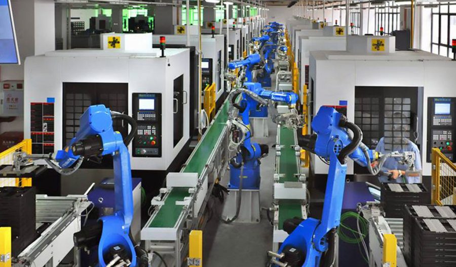
At BE-CU China Metal Spinning company, we make the most of our equipment while monitoring signs of excess wear and stress. In addition, we look into newer, modern equipment and invest in those that can support or increase our manufacturing capabilities. Our team is very mindful of our machines and tools, so we also routinely maintain them to ensure they don’t negatively impact your part’s quality and productivity.
Talk to us today about making a rapid prototype with our CNC metal spinning service. Get a direct quote by chatting with us here or request a free project review.
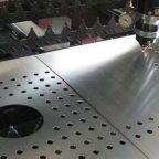
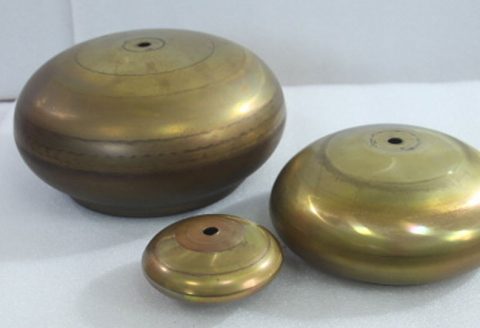
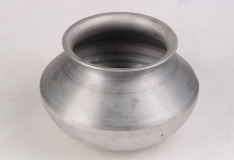
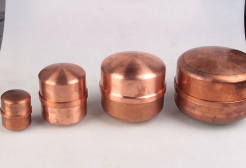
BE-CU China CNC Metal Spinning service include : CNC Metal Spinning,Metal Spinning Die,Laser Cutting, Tank Heads Spinning,Metal Hemispheres Spinning,Metal Cones Spinning,Metal Dish-Shaped Spinning,Metal Trumpet Spinning,Metal Venturi Spinning,Aluminum Spinning Products,Stainless Steel Spinning Products,Copper Spinning Products,Brass Spinning Products,Steel Spinning Product,Metal Spinnin LED Reflector,Metal Spinning Pressure Vessel,
