Metal spinning is a versatile manufacturing process used to create seamless, hollow components by rotating a metal blank and applying localized force to shape it over a mandrel or tool. Traditionally, this process has been limited to axisymmetric (rotationally symmetric) geometries due to the constraints of mandrel-based forming and uniform load distribution. However, recent advancements in computer numerical control (CNC) technology, finite element modeling (FEM), and innovative die design methodologies have expanded the capabilities of metal spinning to include special-shaped cross-section components—non-cylindrical geometries with asymmetric features. These advancements have necessitated the development of sophisticated techniques for asymmetric load modeling and reverse die design, which are critical for achieving high precision, minimizing material waste, and optimizing the mechanical properties of spun aluminum components.
This article explores the principles, methodologies, and technological innovations in asymmetric load modeling and reverse die design for special-shaped cross-section aluminum spinning components. It delves into the mechanics of asymmetric spinning, the role of computational modeling, experimental validations, and the integration of reverse engineering principles in die design. The discussion is supported by detailed comparisons of techniques, materials, and outcomes, presented in tabular form to enhance clarity and scientific rigor. The focus is on aluminum alloys due to their widespread use in industries such as aerospace, automotive, and consumer electronics, where lightweight, durable, and complex-shaped components are in high demand.
Fundamentals of Metal Spinning
Overview of Metal Spinning
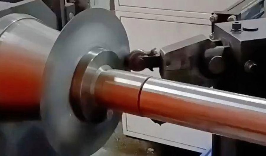
Metal spinning, also known as spin forming or spinning, is a cold-forming process that transforms a flat metal blank into a hollow, seamless component by rotating it at high speed and applying localized pressure with a roller or tool. The process is typically performed on a lathe or CNC spinning machine, where the blank is clamped against a mandrel that defines the final shape. Traditional spinning is ideal for producing axisymmetric parts such as cones, cylinders, and hemispheres, as the rotational symmetry simplifies load distribution and toolpath design. However, the production of non-cylindrical, asymmetric components introduces significant challenges, including uneven load distribution, complex deformation patterns, and the need for flexible tooling.
Challenges in Asymmetric Spinning
Asymmetric spinning involves forming components with non-circular cross-sections, such as ellipses, rectangles, or irregular shapes, which deviate from the rotational symmetry of traditional spinning. These geometries result in asymmetric load distributions, where forces and stresses vary across the workpiece, leading to challenges such as:
- Uneven Wall Thickness: Non-uniform deformation can cause thinning or thickening in specific regions, affecting structural integrity.
- Wrinkling and Buckling: Asymmetric loads may induce localized instabilities, leading to surface defects.
- Toolpath Complexity: Achieving the desired geometry requires precise control of roller paths, often necessitating advanced CNC systems.
- Mandrel Limitations: Traditional mandrels are rigid and axisymmetric, making them unsuitable for asymmetric shapes without significant modification.
To address these challenges, researchers and engineers have developed asymmetric load modeling techniques and reverse die design methodologies, leveraging computational tools and innovative tooling concepts.
Asymmetric Load Modeling in Spinning
Principles of Load Modeling
Load modeling in metal spinning involves predicting the forces, stresses, and strains experienced by the workpiece during deformation. For axisymmetric components, load distribution is relatively uniform due to rotational symmetry, allowing for simplified analytical models. However, in asymmetric spinning, the load distribution is non-uniform, requiring advanced computational models to capture the complex interplay of forces. Key aspects of asymmetric load modeling include:
- Force Components: The roller applies axial, radial, and tangential forces, which vary depending on the geometry of the workpiece and the roller path.
- Stress and Strain Distribution: Asymmetric shapes result in heterogeneous stress fields, with localized areas of high stress concentration.
- Material Behavior: Aluminum alloys exhibit anisotropic behavior, strain-rate sensitivity, and temperature-dependent properties, which must be incorporated into models.
Finite element modeling (FEM) is the cornerstone of asymmetric load modeling, enabling engineers to simulate the spinning process and predict outcomes such as wall thickness distribution, residual stresses, and potential defects.
Finite Element Modeling (FEM) for Asymmetric Spinning
Finite element modeling is a computational technique that discretizes the workpiece into a mesh of elements to simulate its mechanical behavior under applied loads. In asymmetric spinning, FEM is used to:
- Analyze plastic flow patterns and deformation mechanisms.
- Predict wall thickness variations and potential failure modes (e.g., wrinkling, cracking).
- Optimize roller paths and process parameters to achieve the desired geometry.
Commercial FEM software packages, such as DEFORM-3D, LS-DYNA, and Abaqus, are commonly used for these simulations. These tools allow for the incorporation of material properties, boundary conditions, and contact interactions between the roller and workpiece. For example, a study by Xia et al. (2014) utilized DEFORM-3D to analyze the plastic flow of an asymmetric middle-tube during spinning, demonstrating improved shape accuracy with generic rollers compared to profile rollers.
Key FEM Parameters
The accuracy of FEM simulations depends on several parameters, including:
- Mesh Type and Density: A finer mesh improves accuracy but increases computational cost. Shell elements are often used for thin-walled components, while solid elements are preferred for high-curvature regions.
- Material Models: Aluminum alloys, such as A6061 or A1100-O, are modeled using elastic-plastic constitutive equations, often incorporating strain-rate and temperature effects.
- Contact and Friction: The interaction between the roller and workpiece is modeled using Coulomb friction or shear friction models, with coefficients typically ranging from 0.1 to 0.3.
- Boundary Conditions: The workpiece is constrained at the spindle and tailstock, with rotational velocity and roller feed rates specified.
Example FEM Analysis
Consider a hypothetical case of spinning an elliptical aluminum tube with a wall thickness of 1.5 mm. The FEM model might include:
- Material: A6061 aluminum alloy (Young’s modulus: 70 GPa, Poisson’s ratio: 0.3, yield strength: 145 MPa).
- Mesh: A 4-node shell element mesh with 10,000 elements for the workpiece.
- Roller Path: A multi-pass trajectory with a feed rate of 0.5 mm/rev and a spindle speed of 200 RPM.
- Output: Stress distribution, strain energy, and wall thickness variation.
The simulation would reveal areas of high stress concentration near the major axis of the ellipse, guiding adjustments to the roller path to minimize thinning.
Analytical Models for Asymmetric Loads
While FEM provides detailed insights, analytical models offer a computationally efficient alternative for preliminary design. These models simplify the spinning process into a series of equations based on assumptions such as plane strain or membrane theory. For asymmetric spinning, analytical models focus on:
- Shear-Necking and Stretch-Necking: Two primary deformation modes identified in dieless necking-in spinning. Shear-necking leads to thickening, while stretch-necking causes thinning, influencing wall thickness distribution.
- Force Equilibrium: Balancing axial, radial, and tangential forces to predict roller loads and workpiece deformation.
- Geometric Constraints: Accounting for the non-circular cross-section and its impact on load distribution.
An analytical model proposed by Allwood et al. (2011) demonstrated that replacing a solid mandrel with three rollers could replicate the load distribution of asymmetric shapes, validated through trials on 1.4 mm thick aluminum blanks.
Experimental Validation
Experimental validation is critical to ensure the accuracy of load models. Trials typically involve spinning aluminum blanks on CNC lathes and measuring outcomes such as:
- Wall Thickness: Using ultrasonic or laser-based thickness gauges to verify uniformity.
- Surface Quality: Inspecting for defects like wrinkling or surface roughness.
- Forming Forces: Measuring axial, radial, and tangential forces with load cells.
A study by Jia et al. (2017) validated a die-less shear spinning process for an asymmetric conical part, showing good agreement between FEM predictions and experimental measurements of wall thickness and shape accuracy.
Reverse Die Design Technology
Principles of Reverse Die Design
Reverse die design, a subset of reverse engineering, involves working backward from the desired component geometry to determine the optimal die or tooling configuration. In the context of asymmetric spinning, reverse die design aims to:
- Define the initial blank shape and dimensions.
- Design flexible tooling (e.g., generic rollers or adjustable mandrels) to accommodate non-circular cross-sections.
- Optimize roller paths to achieve the target geometry with minimal defects.
This approach contrasts with forward die design, where the tooling is designed first, and the component geometry is derived through trial and error. Reverse die design leverages computational tools and experimental data to streamline the process, reducing costs and development time.
Reverse Engineering in Die Design
Reverse engineering in die design involves several steps:
- Shape Acquisition: Capturing the geometry of the desired component using 3D scanning (e.g., laser or photogrammetry) or CAD models.
- Surface Reconstruction: Creating a digital model of the component surface using software like Geomagic or CATIA.
- Blank Shape Optimization: Determining the initial blank shape through iterative simulations to minimize material waste and ensure uniform deformation.
- Toolpath Generation: Designing roller paths that account for asymmetric load distribution and material flow.
A study by Huang et al. (2009) demonstrated the use of handheld laser scanners for surface reconstruction in reverse engineering, achieving high accuracy in CAD model creation for complex stamping dies.
Flexible Tooling Concepts
Traditional spinning relies on rigid mandrels, which are costly and inflexible for asymmetric shapes. Recent innovations have introduced flexible tooling concepts, such as:
- Generic Rollers: Small-radius rollers (e.g., 2 mm nose radius) that can form arbitrary shapes without a dedicated mandrel.
- Multi-Roller Systems: Replacing a single mandrel with three or more rollers to replicate the load distribution of asymmetric shapes.
- Dieless Spinning: Eliminating the mandrel entirely, relying on precise roller control to shape the workpiece.
These concepts enhance the flexibility of the spinning process, allowing for rapid prototyping and small-batch production of special-shaped components.
Toolpath Generation for Asymmetric Spinning
Toolpath generation is a critical aspect of reverse die design, as it determines the roller’s trajectory to achieve the desired geometry. Key considerations include:
- Synchronization: Coordinating roller movement with spindle rotation to ensure uniform deformation.
- Multi-Pass Strategies: Using multiple forming passes to gradually shape the workpiece, reducing the risk of defects.
- Optimization Algorithms: Employing genetic algorithms or neural networks to optimize toolpaths based on FEM simulations.
Russo and Loukaides (2016) proposed a toolpath generation method for mandrel-free asymmetric spinning, achieving successful formation of elliptical and rectangular components from thin aluminum sheets.
Aluminum Alloys in Asymmetric Spinning
Material Properties
Aluminum alloys are widely used in spinning due to their excellent formability, lightweight nature, and corrosion resistance. Common alloys for asymmetric spinning include:
- A1100-O: Commercially pure aluminum with high ductility, ideal for complex shapes but with lower strength.
- A6061: A heat-treatable alloy with good strength and formability, commonly used in aerospace and automotive applications.
- A7075: A high-strength alloy used in demanding applications, though its lower ductility requires careful process control.
Table 1 compares the mechanical properties of these alloys:
| Alloy | Young’s Modulus (GPa) | Yield Strength (MPa) | Ultimate Tensile Strength (MPa) | Elongation (%) |
|---|---|---|---|---|
| A1100-O | 70 | 35 | 90 | 35 |
| A6061 | 70 | 145 | 240 | 20 |
| A7075 | 72 | 420 | 560 | 10 |
Material Behavior in Asymmetric Spinning
During asymmetric spinning, aluminum alloys exhibit complex behavior due to:
- Anisotropy: Variations in mechanical properties depending on the rolling direction of the sheet.
- Strain-Rate Sensitivity: Higher strain rates can increase flow stress, affecting deformation patterns.
- Temperature Effects: Hot spinning reduces deformation resistance but may alter microstructure and mechanical properties.
Hot spinning of A7075, as studied by Zhao et al. (2017), showed increased equivalent strain with successive passes, highlighting the need for precise temperature control to prevent cracking.
Process Optimization and Control
Optimization Techniques
Optimizing the asymmetric spinning process involves balancing multiple objectives, such as minimizing wall thickness variation, reducing forming forces, and improving surface quality. Common optimization techniques include:
- Genetic Algorithms (GAs): Used to optimize roller paths and process parameters by iteratively evaluating multiple configurations. Xu’s research on asymmetric excavation retaining structures demonstrated a 30% improvement in search efficiency using enhanced GAs.
- Neural Networks: Employed to predict deformation outcomes based on historical data, as shown by Opritescu and Volk (2015) for L-shaped profiles.
- Model Predictive Control (MPC): Used to dynamically adjust roller paths based on real-time feedback, as proposed by Yang et al. (2009).
Process Parameters
Key process parameters in asymmetric spinning include:
- Roller Feed Rate: Typically 0.1–1.0 mm/rev, affecting deformation rate and surface quality.
- Spindle Speed: Ranges from 100–500 RPM, influencing heat generation and material flow.
- Number of Passes: Multi-pass strategies (3–10 passes) reduce localized stresses and improve shape accuracy.
- Roller Nose Radius: Smaller radii (e.g., 2 mm) enhance precision for complex shapes but may increase forming forces.
Table 2 compares the impact of process parameters on spinning outcomes:
| Parameter | Range | Effect on Wall Thickness | Effect on Surface Quality | Effect on Forming Forces |
|---|---|---|---|---|
| Roller Feed Rate | 0.1–1.0 mm/rev | Higher rates increase thinning | Higher rates reduce quality | Higher rates increase forces |
| Spindle Speed | 100–500 RPM | Higher speeds reduce thinning | Higher speeds improve quality | Minimal impact |
| Number of Passes | 3–10 | More passes reduce variation | More passes improve quality | More passes reduce forces |
| Roller Nose Radius | 2–10 mm | Smaller radius increases thinning | Smaller radius improves precision | Smaller radius increases forces |
Real-Time Control Systems
Real-time control systems enhance process reliability by monitoring and adjusting parameters during spinning. Arai (2003) developed a control system using integrated force sensors to regulate roller trajectories, ensuring forces remained within safe limits for asymmetric parts.
Applications and Case Studies
Aerospace Components
Asymmetric spinning is widely used in aerospace for producing components such as elliptical fuel tank caps and non-circular ducting. A case study by Shimizu (2010) demonstrated the formation of an asymmetric truncated elliptical-cone-shaped part using a CNC spinning machine, achieving high shape accuracy with minimal thinning.
Automotive Parts
In the automotive industry, asymmetric spinning is used for lightweight components like suspension brackets and exhaust manifolds. The ability to produce complex shapes with uniform wall thickness reduces vehicle weight and improves fuel efficiency.
Consumer Electronics
Asymmetric spinning is applied in consumer electronics to produce thin-walled, non-cylindrical casings for devices like smartphones and laptops. A study on hot extrusion of A6061 clips for cell phones validated FEM predictions of thickness distribution, demonstrating the process’s suitability for precision components.
Comparative Analysis
Comparison of Spinning Techniques
Table 3 compares conventional spinning, asymmetric spinning with mandrels, and dieless asymmetric spinning:
| Technique | Mandrel Requirement | Shape Flexibility | Tooling Cost | Wall Thickness Uniformity | Applications |
|---|---|---|---|---|---|
| Conventional Spinning | Rigid mandrel | Low (axisymmetric) | High | High | Cylinders, cones, hemispheres |
| Asymmetric Spinning with Mandrel | Dedicated mandrel | Moderate | High | Moderate | Elliptical cones, rectangular boxes |
| Dieless Asymmetric Spinning | None | High | Low | Moderate to high | Complex, non-circular shapes |
Comparison of Modeling Approaches
Table 4 compares FEM and analytical modeling for asymmetric spinning:
| Modeling Approach | Computational Cost | Accuracy | Ease of Use | Applications |
|---|---|---|---|---|
| Finite Element Modeling | High | High | Complex | Detailed process optimization |
| Analytical Modeling | Low | Moderate | Simple | Preliminary design, quick iterations |
Future Directions
Advancements in Computational Modeling
The development of more efficient FEM algorithms and hybrid models combining analytical and numerical approaches will enhance the accuracy and speed of asymmetric load modeling. Machine learning techniques, such as neural networks, are expected to play a larger role in predicting deformation outcomes and optimizing toolpaths.
Novel Tooling Solutions
The adoption of adaptive rollers and reconfigurable tooling systems will further reduce the need for dedicated mandrels, lowering costs and enabling rapid prototyping. Research into 3D-printed rollers with customized geometries is also promising.
Sustainable Manufacturing
Asymmetric spinning can contribute to sustainable manufacturing by minimizing material waste and enabling the use of recycled aluminum alloys. The integration of carbon emission considerations, as explored by Xu in excavation engineering, could be adapted to spinning processes to align with environmental goals.
Conclusion
Asymmetric load modeling and reverse die design are pivotal in advancing the capabilities of metal spinning for special-shaped cross-section aluminum components. By leveraging FEM, analytical models, and flexible tooling, engineers can overcome the limitations of traditional spinning, achieving high precision and efficiency in producing complex geometries. The integration of reverse engineering principles streamlines the design process, while experimental validations ensure reliability. As the demand for lightweight, durable, and customized components grows in industries like aerospace, automotive, and electronics, these technologies will continue to evolve, driven by computational advancements and innovative tooling solutions. The comprehensive tables provided in this article highlight the key parameters, techniques, and outcomes, offering a scientific foundation for further research and industrial applications.
Maximize Tooling and CNC Metal Spinning Capabilities.
At BE-CU China Metal Spinning company, we make the most of our equipment while monitoring signs of excess wear and stress. In addition, we look into newer, modern equipment and invest in those that can support or increase our manufacturing capabilities. Our team is very mindful of our machines and tools, so we also routinely maintain them to ensure they don’t negatively impact your part’s quality and productivity.
Talk to us today about making a rapid prototype with our CNC metal spinning service. Get a direct quote by chatting with us here or request a free project review.
BE-CU China CNC Metal Spinning service include : CNC Metal Spinning,Metal Spinning Die,Laser Cutting, Tank Heads Spinning,Metal Hemispheres Spinning,Metal Cones Spinning,Metal Dish-Shaped Spinning,Metal Trumpet Spinning,Metal Venturi Spinning,Aluminum Spinning Products,Stainless Steel Spinning Products,Copper Spinning Products,Brass Spinning Products,Steel Spinning Product,Metal Spinnin LED Reflector,Metal Spinning Pressure Vessel,