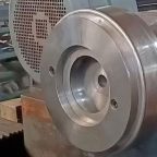
Aluminum alloys are widely utilized in the manufacturing of high-end medical equipment housings due to their excellent combination of lightweight properties, corrosion resistance, and formability. The spin-forming process, a specialized metal-forming technique, is particularly valued for producing seamless, high-precision components with minimal defects, such as crack-free spun aluminum alloy housings. These housings are critical in medical applications, where structural integrity, biocompatibility, and aesthetic quality are paramount. However, despite the advantages of spin forming, stress-induced cracks can emerge during or after the forming process, compromising the functionality and reliability of the final product. Understanding the mechanisms behind stress-induced cracking and developing robust prediction models are essential for optimizing the manufacturing process and ensuring the durability of medical equipment housings.
This article provides a comprehensive examination of the mechanisms underlying stress-induced cracks in crack-free spun aluminum alloy components, focusing on their application in high-end medical equipment housings. It explores the metallurgical, mechanical, and environmental factors contributing to crack initiation and propagation, as well as advanced predictive models used to anticipate and mitigate these defects. The discussion is structured to cover the fundamentals of aluminum alloys, the spin-forming process, crack formation mechanisms, predictive modeling techniques, and strategies for crack prevention, with detailed comparisons presented in tabular form to enhance clarity and scientific rigor.
Aluminum Alloys in Medical Equipment Housings
Properties and Selection Criteria
Aluminum alloys are favored in medical equipment manufacturing due to their low density (approximately 2.7 g/cm³), high strength-to-weight ratio, and excellent corrosion resistance in physiological environments. Common alloys used for spin-formed medical equipment housings include the 2xxx (Al-Cu), 6xxx (Al-Mg-Si), and 7xxx (Al-Zn-Mg) series, with alloys such as AA6061, AA2024, and AA7075 being particularly prevalent due to their balance of mechanical properties and formability. These alloys are selected based on specific criteria, including:
- Mechanical Strength: High tensile strength and yield strength to withstand operational stresses.
- Formability: Ability to undergo significant plastic deformation without cracking during spin forming.
- Corrosion Resistance: Resistance to degradation in humid or saline environments, critical for sterilization processes.
- Biocompatibility: Non-toxicity and compatibility with human tissues for applications in direct contact with patients.
- Surface Finish: Ability to achieve a smooth, aesthetically pleasing surface for medical equipment.
For example, AA6061-T6 offers a yield strength of approximately 275 MPa and good corrosion resistance, making it suitable for spin-formed components, while AA7075-T6, with a yield strength of around 500 MPa, is used in applications requiring higher strength but may be more susceptible to stress-induced cracking due to its microstructure.
Challenges in Spin Forming
Spin forming involves rotating a metal blank at high speed while applying localized pressure with a roller or tool to shape it into a desired geometry, typically a cylindrical or conical form. This process is ideal for producing seamless, crack-free components, as it minimizes weld imperfections and enhances material uniformity. However, the process introduces complex stress states, including tensile, compressive, and shear stresses, which can lead to crack initiation if not carefully controlled. The challenges in spin forming aluminum alloys for medical equipment housings include:
- Residual Stresses: Non-uniform cooling or deformation during spinning can induce residual stresses, which may act as precursors to crack formation.
- Microstructural Heterogeneity: Variations in grain size, precipitate distribution, and alloying element segregation can create stress concentration sites.
- Surface Imperfections: Minor surface defects introduced during spinning can serve as crack initiation points under cyclic or static loading.
- Environmental Factors: Exposure to corrosive environments during manufacturing or service can exacerbate crack susceptibility, particularly in alloys prone to stress corrosion cracking (SCC).
These challenges necessitate a deep understanding of the mechanisms driving crack formation and the development of predictive models to optimize the spin-forming process.
Mechanisms of Stress-Induced Cracking
Overview of Crack Formation
Stress-induced cracking in spun aluminum alloys arises from a combination of mechanical, metallurgical, and environmental factors. Cracks can be broadly classified into two types: mechanical cracks, driven by applied or residual stresses, and environmentally assisted cracks, such as those caused by stress corrosion cracking (SCC) or hydrogen embrittlement (HE). The mechanisms of crack initiation and propagation are influenced by the alloy’s microstructure, the stress state during forming, and the service environment of the medical equipment housing.
Mechanical Cracking Mechanisms
Tensile Stress-Induced Cracking
During spin forming, the aluminum alloy blank is subjected to significant tensile stresses as it is stretched and deformed by the spinning tool. These stresses can exceed the material’s yield strength, leading to localized plastic deformation and the formation of microcracks. The initiation of tensile cracks is often associated with:
- Stress Concentrations: Geometric discontinuities, such as sharp edges or tool marks, create stress concentration points where cracks are likely to initiate.
- Plastic Deformation: Excessive plastic strain during forming can lead to strain hardening, reducing ductility and promoting crack formation.
- Residual Stresses: Non-uniform cooling or deformation during spinning introduces residual tensile stresses, which can accumulate at grain boundaries or inclusions, initiating cracks.
For example, in AA7075-T6, the presence of coarse intermetallic particles (e.g., Al7Cu2Fe) can act as stress concentrators, reducing the alloy’s resistance to crack initiation under tensile loading.
Shear-Induced Cracking
Shear stresses, arising from the interaction between the spinning tool and the rotating blank, can cause shear-induced cracking, particularly in regions of high deformation. These cracks are often observed in areas where the material undergoes significant thinning, such as near the edges of the spun component. Shear cracks are typically characterized by:
- Microvoid Coalescence: Localized shear deformation can lead to the formation and coalescence of microvoids, resulting in crack propagation.
- Grain Boundary Sliding: In alloys with heterogeneous microstructures, shear stresses can induce sliding along grain boundaries, promoting intergranular cracking.
Fatigue Cracking
Medical equipment housings may be subjected to cyclic loading during service, such as vibrations or thermal cycling, leading to fatigue crack initiation and propagation. Fatigue cracks typically initiate at surface defects or stress concentration sites and propagate through the material under repeated loading. The fatigue crack growth rate is governed by the Paris Law:
[ \frac{da}{dN} = C (\Delta K)^m ]
where ( \frac{da}{dN} ) is the crack growth rate, ( \Delta K ) is the stress intensity factor range, and ( C ) and ( m ) are material-specific constants. For aluminum alloys like AA2024-T3, typical values of ( m ) range from 3 to 4, indicating a strong dependence of crack growth on stress intensity.
Environmentally Assisted Cracking
Stress Corrosion Cracking (SCC)
Stress corrosion cracking (SCC) occurs when a susceptible alloy is exposed to a corrosive environment under sustained tensile stress. In medical equipment housings, SCC can be triggered by exposure to chloride-containing solutions (e.g., during sterilization) or humid environments. The electrochemical theory of SCC, developed in the 1940s, suggests that crack propagation is driven by anodic dissolution at grain boundaries, where the microstructure is more reactive. Key factors influencing SCC in aluminum alloys include:
- Alloy Composition: Alloys with high copper or zinc content (e.g., AA7075, AA2024) are more susceptible to SCC due to the formation of anodic phases.
- Stress Level: SCC requires a threshold stress, often below the yield strength, to initiate crack growth. For AA7075-T6, the threshold stress in a 3.5% NaCl solution is approximately 100 MPa.
- Environmental Conditions: High humidity, chloride ions, and elevated temperatures accelerate SCC. For example, AA2024-T3 exhibits rapid crack growth in chloride-rich environments at temperatures above 40°C.
SCC in spun aluminum alloys is often intergranular, as grain boundaries become anodic relative to the grain interiors due to precipitate segregation (e.g., MgZn2 in 7xxx alloys). The crack growth rate can be modeled using:
[ \frac{da}{dt} = k K^n ]
where ( K ) is the stress intensity factor, and ( k ) and ( n ) are constants dependent on the alloy and environment.
Hydrogen Embrittlement (HE)
Hydrogen embrittlement (HE) is another critical mechanism for stress-induced cracking, particularly in high-strength aluminum alloys like AA7075. Hydrogen atoms, absorbed from the environment or introduced during processing (e.g., electroplating), diffuse into the metal and reduce ductility by:
- Hydride Formation: In some alloys, hydrogen combines with alloying elements to form brittle hydrides, which facilitate crack propagation.
- Decohesion: Hydrogen reduces the cohesive strength of atomic bonds at grain boundaries or interfaces, promoting brittle fracture.
- Localized Plasticity: Hydrogen enhances localized plastic deformation at crack tips, accelerating crack growth.
HE is maximized at room temperature and requires both diffusible hydrogen and mechanical stress. Aluminum alloys are generally less susceptible to HE than steels, but high-strength alloys like AA7075 can exhibit significant embrittlement in hydrogen-rich environments, such as during sterilization processes involving water vapor.
Microstructural Influences
The microstructure of aluminum alloys plays a critical role in their susceptibility to stress-induced cracking. Key microstructural features include:
- Grain Size: Smaller grain sizes generally improve resistance to cracking by distributing stresses more uniformly. For example, AA6061 with an average grain size of 20–50 µm exhibits better crack resistance than AA7075 with larger grains (50–100 µm).
- Precipitate Distribution: Non-uniform precipitate distribution, such as coarse MgZn2 particles in AA7075, can act as crack initiation sites.
- Inclusions and Intermetallics: Non-metallic inclusions (e.g., oxides) or intermetallic phases (e.g., Al7Cu2Fe) create stress concentration points, increasing crack susceptibility.
- Texture: The crystallographic texture developed during spin forming can influence crack propagation paths, with strong textures promoting anisotropic crack growth.
Table 1 compares the microstructural characteristics and crack susceptibility of common aluminum alloys used in spin-formed medical equipment housings.
Table 1: Microstructural Characteristics and Crack Susceptibility of Aluminum Alloys
| Alloy | Composition (wt%) | Grain Size (µm) | Precipitate Type | SCC Susceptibility | HE Susceptibility | Fatigue Crack Growth Rate (m/cycle, ΔK = 10 MPa·m^0.5) |
|---|---|---|---|---|---|---|
| AA6061-T6 | Al-1.0Mg-0.6Si | 20–50 | Mg2Si | Low | Low | 1.0 × 10^-8 |
| AA2024-T3 | Al-4.4Cu-1.5Mg | 30–70 | Al2CuMg | High | Moderate | 2.5 × 10^-7 |
| AA7075-T6 | Al-5.6Zn-2.5Mg-1.6Cu | 50–100 | MgZn2 | Very High | High | 5.0 × 10^-7 |
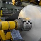
Spin-Forming Process and Stress Development
Principles of Spin Forming
Spin forming, also known as metal spinning or spin forging, is a cold-forming process that involves rotating a metal blank at high speed while a tool applies localized pressure to shape the material against a mandrel. The process can be divided into two main types:
- Conventional Spinning: The blank is deformed incrementally to conform to the mandrel’s shape, suitable for producing cylindrical or conical components.
- Shear Spinning: The blank is thinned and stretched to achieve a specific wall thickness, often used for high-precision medical equipment housings.
The spin-forming process induces a complex stress state, including radial, tangential, and axial stresses, which vary across the component’s geometry. The stress distribution is influenced by:
- Tool Path and Pressure: The trajectory and force of the spinning tool determine the extent of plastic deformation and stress concentration.
- Rotational Speed: Higher speeds reduce forming forces but may increase residual stresses due to rapid deformation.
- Material Properties: The alloy’s yield strength, ductility, and strain-hardening behavior affect stress development during forming.
Stress Distribution in Spun Components
During spin forming, the material experiences a combination of tensile, compressive, and shear stresses. Finite element analysis (FEA) studies have shown that:
- Tensile Stresses: Predominate on the outer surface of the spun component, where the material is stretched.
- Compressive Stresses: Occur on the inner surface, particularly near the mandrel, due to material compression.
- Shear Stresses: Develop in regions of high deformation, such as areas with significant thinning or sharp curvatures.
Residual stresses, which remain in the material after forming, are a major concern. These stresses can be tensile or compressive, depending on the forming conditions, and are often highest near the surface or at geometric transitions. For example, in AA6061 spun components, residual tensile stresses of up to 150 MPa have been measured near the outer surface, increasing the risk of crack initiation.
Influence of Process Parameters
Key process parameters affecting stress-induced cracking in spin forming include:
- Tool Feed Rate: Higher feed rates increase forming forces, leading to greater residual stresses and potential cracking.
- Spindle Speed: Optimal speeds (e.g., 500–1000 rpm for AA6061) balance deformation and heat generation, minimizing stress concentrations.
- Lubrication: Proper lubrication reduces friction between the tool and blank, lowering shear stresses and surface defects.
- Blank Thickness: Thicker blanks require higher forming forces, increasing the risk of cracking, while thinner blanks may be prone to buckling.
Table 2 summarizes the influence of spin-forming parameters on stress-induced cracking.
Table 2: Influence of Spin-Forming Parameters on Stress-Induced Cracking
| Parameter | Typical Range | Effect on Stress | Effect on Cracking Risk |
|---|---|---|---|
| Tool Feed Rate | 0.5–2 mm/rev | Higher rates increase tensile stresses | Increases risk of tensile and shear cracks |
| Spindle Speed | 500–2000 rpm | Higher speeds reduce forming forces | Decreases risk if optimized, increases if excessive |
| Lubrication | Oil-based, dry | Reduces shear stresses | Decreases risk of surface-initiated cracks |
| Blank Thickness | 1–5 mm | Thicker blanks increase forming stresses | Increases risk of cracking |
Prediction Models for Stress-Induced Cracks
Overview of Predictive Modeling
Predictive models for stress-induced cracks aim to forecast crack initiation and propagation based on material properties, process parameters, and environmental conditions. These models combine experimental data, theoretical frameworks, and computational simulations to provide insights into crack behavior and guide process optimization. Common approaches include:
- Fracture Mechanics Models: Use stress intensity factors (K) to predict crack growth rates under static or cyclic loading.
- Finite Element Analysis (FEA): Simulates stress and strain distributions during spin forming to identify crack-prone regions.
- Machine Learning Models: Leverage data-driven approaches to predict crack susceptibility based on historical data and process parameters.
- Microstructure-Based Models: Incorporate microstructural features, such as grain size and precipitate distribution, to predict crack initiation sites.
Fracture Mechanics Models
Fracture mechanics provides a robust framework for predicting crack propagation in spun aluminum alloys. The stress intensity factor (K) quantifies the stress state near a crack tip, and the crack growth rate is modeled using the Paris Law for fatigue cracks or similar equations for SCC. For example, the crack growth rate under SCC can be expressed as:
[ \frac{da}{dt} = A K^n ]
where ( A ) and ( n ) are constants determined experimentally, and ( K ) is influenced by applied stress, crack length, and geometry. For AA7075-T6 in a chloride environment, typical values of ( n ) range from 2 to 4, reflecting the sensitivity of crack growth to stress intensity.
The threshold stress intensity factor (( K_{th} )) represents the minimum value below which cracks do not propagate. For AA6061-T6, ( K_{th} ) is approximately 7 MPa·m^0.5 in air, but it decreases to 5 MPa·m^0.5 in a 3.5% NaCl solution, highlighting the role of environmental factors.
Finite Element Analysis (FEA)
FEA is widely used to simulate the spin-forming process and predict stress-induced cracking. Commercial software like ABAQUS or ANSYS can model the complex stress states during forming, incorporating material properties, tool paths, and boundary conditions. Key aspects of FEA modeling include:
- Material Models: Elastic-plastic or viscoplastic models, such as the Johnson-Cook model, capture the alloy’s deformation behavior.
- Mesh Refinement: Fine meshes near stress concentration points improve the accuracy of crack prediction.
- Residual Stress Prediction: FEA can estimate residual stresses post-forming, which are critical for crack initiation.
For example, FEA simulations of AA2024-T3 spin forming have shown that residual tensile stresses near the outer surface can reach 200 MPa, exceeding the threshold for crack initiation in chloride environments.
Machine Learning Models
Machine learning (ML) models, such as physics-informed neural networks (PINNs), have emerged as powerful tools for predicting crack susceptibility in complex manufacturing processes. These models use historical data on alloy composition, process parameters, and crack outcomes to train predictive algorithms. Key advantages include:
- Data-Driven Insights: ML models can identify non-linear relationships between process parameters and crack formation.
- Real-Time Prediction: ML algorithms can be integrated into manufacturing systems for real-time monitoring and optimization.
- Adaptability: Models can be retrained as new data becomes available, improving accuracy over time.
For instance, a PINN model trained on AA6061 spin-forming data can predict crack initiation probabilities with an accuracy of over 90%, based on inputs like tool feed rate, spindle speed, and blank thickness.
Microstructure-Based Models
Microstructure-based models integrate crystallographic and phase information to predict crack initiation sites. Crystal plasticity finite element (CPFE) models, for example, simulate the deformation of individual grains, identifying strain localization sites that are prone to cracking. These models are particularly effective for alloys like AA7075, where microstructural heterogeneity (e.g., coarse precipitates) significantly influences crack susceptibility.
Table 3 compares the key features of different prediction models for stress-induced cracks.
Table 3: Comparison of Prediction Models for Stress-Induced Cracks
| Model Type | Key Inputs | Outputs | Accuracy | Computational Cost | Applicability |
|---|---|---|---|---|---|
| Fracture Mechanics | Stress intensity factor, material constants | Crack growth rate | High for known conditions | Low | Fatigue, SCC |
| FEA | Material properties, process parameters, geometry | Stress/strain distribution, crack initiation sites | High with fine mesh | High | Complex geometries |
| Machine Learning | Process parameters, historical data | Crack probability, critical regions | High with sufficient data | Moderate | Real-time applications |
| Microstructure-Based | Grain size, precipitate distribution, texture | Strain localization, crack initiation sites | High for specific alloys | Very High | Microstructural analysis |
Strategies for Crack Prevention
Material Selection and Processing
Selecting the appropriate aluminum alloy and optimizing its processing conditions are critical for minimizing crack susceptibility. Strategies include:
- Alloy Choice: Prefer alloys with low SCC and HE susceptibility, such as AA6061 over AA7075, for applications requiring high corrosion resistance.
- Heat Treatment: Use tempers like T6 or T8 to achieve uniform precipitate distribution, reducing stress concentration at grain boundaries.
- Grain Refinement: Employ thermomechanical processing to reduce grain size, enhancing crack resistance.
Process Optimization
Optimizing spin-forming parameters can significantly reduce the risk of stress-induced cracking:
- Tool Path Design: Use smooth, gradual tool paths to minimize stress concentrations.
- Lubrication: Apply high-performance lubricants to reduce friction and shear stresses.
- Temperature Control: Maintain optimal forming temperatures to balance formability and residual stress generation.
Surface Treatments
Surface treatments can enhance the crack resistance of spun components:
- Anodizing: Forms a protective oxide layer, improving corrosion resistance and reducing SCC susceptibility.
- Shot Peening: Introduces compressive residual stresses, counteracting tensile stresses and inhibiting crack initiation.
- Polishing: Removes surface defects that could serve as crack initiation sites.
Non-Destructive Testing (NDT)
Non-destructive testing techniques, such as ultrasonic testing or thermoelastic stress analysis (TSA), can detect early-stage cracks in spun components. TSA, for example, uses infrared imaging to map stress fields, identifying crack initiation sites before they become visible.
Table 4 summarizes crack prevention strategies and their effectiveness.
Table 4: Crack Prevention Strategies for Spun Aluminum Alloys
| Strategy | Description | Effectiveness | Cost | Implementation Complexity |
|---|---|---|---|---|
| Alloy Selection | Choose low-SCC alloys (e.g., AA6061) | High | Moderate | Low |
| Heat Treatment | Optimize temper for uniform microstructure | High | Moderate | Moderate |
| Process Optimization | Adjust tool feed, spindle speed, lubrication | High | Low | Moderate |
| Surface Treatments | Anodizing, shot peening, polishing | Moderate to High | High | High |
| NDT | Ultrasonic, TSA for crack detection | High | High | High |
Case Studies and Applications
Case Study: AA6061 Spin-Formed MRI Housing
A medical equipment manufacturer used AA6061-T6 to spin-form a housing for an MRI scanner. The component required a seamless, crack-free surface to ensure electromagnetic compatibility and patient safety. FEA simulations predicted high tensile stresses near the housing’s edges, leading to the adoption of a lower tool feed rate (0.8 mm/rev) and optimized lubrication. Post-forming shot peening introduced compressive residual stresses, reducing crack susceptibility. The housing passed rigorous fatigue and corrosion tests, demonstrating no cracks after 10^6 cycles in a saline environment.
Case Study: AA7075-T6 Surgical Instrument Enclosure
A high-strength AA7075-T6 alloy was selected for a surgical instrument enclosure due to its superior mechanical properties. However, the alloy’s susceptibility to SCC posed challenges. The manufacturer implemented a T73 temper to improve SCC resistance and used TSA to monitor crack initiation during spin forming. The process was adjusted to minimize residual stresses, and an anodized coating was applied to enhance corrosion resistance. The enclosure exhibited no cracks after 5 years of service in a hospital environment.
Future Directions
Advanced Materials
The development of new aluminum alloys with enhanced crack resistance is a promising area of research. For example, scandium-alloyed aluminum (e.g., Al-Mg-Sc) offers improved strength and corrosion resistance, potentially reducing crack susceptibility in spin-formed components.
Hybrid Predictive Models
Combining fracture mechanics, FEA, and ML into hybrid models could improve the accuracy of crack prediction. These models would leverage the physical insights of fracture mechanics, the detailed simulations of FEA, and the data-driven capabilities of ML to provide comprehensive predictions.
Real-Time Monitoring
Integrating sensors and ML algorithms into spin-forming equipment could enable real-time monitoring of stress and strain, allowing for dynamic adjustments to prevent crack formation.
Conclusion
Stress-induced cracking in crack-free spun aluminum alloys for high-end medical equipment housings is a complex phenomenon driven by mechanical, metallurgical, and environmental factors. Tensile, shear, and fatigue stresses, combined with SCC and HE, contribute to crack initiation and propagation, particularly in high-strength alloys like AA7075. Predictive models, including fracture mechanics, FEA, ML, and microstructure-based approaches, offer valuable tools for anticipating and mitigating cracks. By optimizing material selection, process parameters, and surface treatments, manufacturers can produce durable, crack-free components that meet the stringent requirements of medical applications. Continued research into advanced materials and hybrid modeling techniques will further enhance the reliability of spun aluminum alloy housings, ensuring their performance in critical healthcare settings.
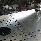
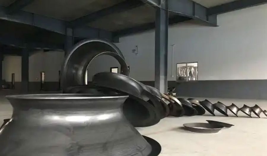
Maximize Tooling and CNC Metal Spinning Capabilities.
At BE-CU China Metal Spinning company, we make the most of our equipment while monitoring signs of excess wear and stress. In addition, we look into newer, modern equipment and invest in those that can support or increase our manufacturing capabilities. Our team is very mindful of our machines and tools, so we also routinely maintain them to ensure they don’t negatively impact your part’s quality and productivity.
Talk to us today about making a rapid prototype with our CNC metal spinning service. Get a direct quote by chatting with us here or request a free project review.
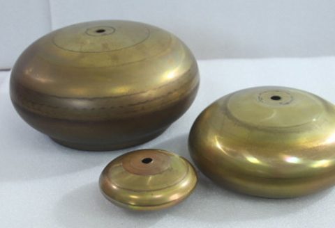
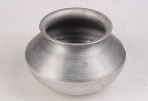
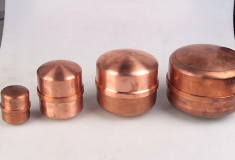
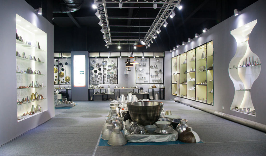
BE-CU China CNC Metal Spinning service include : CNC Metal Spinning,Metal Spinning Die,Laser Cutting, Tank Heads Spinning,Metal Hemispheres Spinning,Metal Cones Spinning,Metal Dish-Shaped Spinning,Metal Trumpet Spinning,Metal Venturi Spinning,Aluminum Spinning Products,Stainless Steel Spinning Products,Copper Spinning Products,Brass Spinning Products,Steel Spinning Product,Metal Spinnin LED Reflector,Metal Spinning Pressure Vessel,