Cam mechanisms, characterized by higher pairings, enable followers to achieve predetermined motion patterns. They present several advantages and disadvantages as follows:
Advantages:
- The motion law of the follower can be arbitrarily designed. Cam mechanisms are suitable for applications requiring precise follower movement and can accommodate intermittent motion. The ratio and number of motion to dwell times can be freely specified. They provide high-speed initiation and reliable, accurate actions.
- By designing the appropriate cam profile, followers can move according to the specified law. Designing medium to low-speed cam motions is relatively straightforward. With the widespread use of CNC machines and computers, especially in recent years, computer-aided design and manufacturing have made cam profile machining much less challenging.
Disadvantages:
- Ensuring good lubrication at higher pair contact points is difficult due to high pressures, leading to wear and tear. Therefore, to maintain necessary lifespan, the transmitted power cannot be excessively high.
- In high-speed cam mechanisms, the dynamic characteristics of higher pair contact points are complex, making precise analysis and design challenging.
In many mechanical devices, especially in automated and semi-automated machinery design, due to production process requirements, mechanisms are often needed to achieve periodic indexing, intermittent motion with moments of pause or dwell. Such mechanisms, whose output curves display periodicity, are known as intermittent motion mechanisms.
Intermittent motion mechanisms find extensive applications in machine tools, chemical, light industry, printing, electronics, packaging, food machinery, and metrological instruments. With advancements in science and technology, and the rise in processing efficiency, high-speed and precision intermittent motion mechanisms are increasingly utilized. Mechanisms used for intermittent motion include ratchet mechanisms, slot wheel mechanisms, pin wheel mechanisms, incomplete gear mechanisms, and cam indexing mechanisms.
Ratchet mechanisms convert the periodic oscillation of a lever into unidirectional intermittent rotation of a ratchet, often used as anti-reversal devices. Slot wheel mechanisms (also known as Geneva mechanisms) convert the continuous rotation of the driving shaft into unidirectional periodic intermittent motion of the driven shaft and are commonly used in various indexing devices. Incomplete involute gear mechanisms convert continuous rotation of the driving gear into intermittent rotation of the driven gear. Their motion to dwell time ratio is not limited by the mechanism’s structure, and they are easy to manufacture. However, due to severe impact at the beginning and end of each intermittent motion, they are generally only used in low-speed, light-load, and non-critical impact applications. Pin wheel mechanisms can be either externally or internally meshed, characterized by a drive pin wheel with pins and a locking convex arc, and a driven star wheel with locking concave arcs, cycloidal teeth, and transition curves.
The follower’s motion starts with gradual acceleration, maintains constant speed, and then decelerates gradually at the end of engagement. Cam indexing mechanisms have the cam as the driver, typically rotating continuously at a constant speed, while the follower is a turntable with multiple rollers, enabling intermittent indexing and positioning. This type of mechanism can achieve precise indexing without additional devices. The motion is characterized by an alternating move-stop-move sequence, which inherently generates acceleration and impact, detrimental to the work process.
Therefore, for high-speed and precision intermittent motion mechanisms, cam mechanisms are preferred. Commonly used cam mechanisms include arc cam indexing mechanisms, cylindrical cam indexing mechanisms, and parallel cam indexing mechanisms. This study focuses on the theoretical analysis and structural design of cylindrical cam indexing mechanisms. The driving component in cylindrical cam indexing mechanisms is a cylindrical cam, with several rollers uniformly distributed along the circumference of the turntable. The axes of the rollers are parallel to the turntable’s axis, and the axes of the cam and turntable intersect perpendicularly. As the rollers rotate, the cam profile pushes the rollers to achieve indexing, while during the dwell phase, two adjacent rollers on the turntable clamp the cam’s annular ridge, stopping the turntable. This mechanism ensures good positioning without additional devices.
The market is flooded with products mostly manufactured by automated machines. Automated machines periodically move and dwell to transfer products to the next workstation during motion and provide sufficient operation time for manipulators at different workstations during dwell. Thus, after processing at multiple workstations, semi-finished products become complete products.
Mechanical engineering is a fundamental industry. With the rapid development of modern technology, mechanical engineering has undergone profound changes, especially with the close integration of computer technology, making modern mechanical technology more complex and advanced than before. Consequently, higher demands are placed on mechanisms that convert continuous motion into intermittent motion in various automatic machines, automatic lines, and semi-automatic lines.
The efficiency and smooth operation of an automatic machine largely depend on the technical performance and stable motion of the cam indexing mechanism, making it a crucial component of automatic machines.
Indexing Motion
In mechanical design, indexing motion mainly includes linear conveyor belts or rotary tables. Both types must meet precise positional accuracy requirements. Cam-driven precision intermittent mechanisms, characterized by high indexing accuracy, suitability for high-speed production, high load capacity, and low maintenance, offer special motion characteristics needed by users. They consist of a cam, follower, driven system, and drive system.
Working Principle of the Follower System
The follower in an indexing system is typically a cylindrical roller fixed to a follower disc, which is usually mounted on the output shaft supported by bearings within the housing, forming the follower system. When the motor drives the system, motion is transmitted to the camshaft, which rotates at a specified speed. The cam profile engages the follower wheel to achieve precision intermittent indexing through the output shaft. During engagement, the cam profile controls and guides the follower’s rotation and dwell to complete the required intermittent motion. The cam rotates at a fixed speed, outputting, pausing, and starting in a periodic cycle.
Characteristics of Cam-Driven Indexing Mechanisms
Cam-driven indexing systems are new transmission devices in automated machinery for high-speed, high-precision intermittent indexing. Utilizing advanced mathematical theories and modern CNC technology for optimal design and precise machining, they offer high indexing accuracy, high speed, good performance, smooth operation, compact structure, small size, light weight, low noise, and long lifespan. Widely used in various automated machinery for intermittent indexing and stepping output, they are essential components for achieving automated, efficient production in light industry, packaging, pharmaceuticals, tobacco, electronics, and chemical industries.
Cam-driven indexing systems can be designed to meet precision and rigidity requirements, with constant engagement between the cam and the follower. The follower is preloaded by varying the axis distance, eliminating any manufacturing tolerances and clearances. This preload is supported by tapered roller bearings on the input and output shafts. The cam controls the entire process, ensuring accuracy. Simple modifications to the cam and meticulous design of the follower, driven, and drive systems minimize engagement impact, achieving precision levels. Rollers with needle bearings reduce friction and wear, extending lifespan and improving accuracy. The speed and acceleration curves of the indexing mechanism can be manually controlled, making it one of the best mechanisms available today.
Common Cam Indexing Mechanisms
1.5.1 Arc Cam Indexing Mechanism
The arc cam indexing mechanism, shown in Figure 1-1, is used for intermittent indexing transmission between two orthogonally intersecting axes. The drive cam is an arc-shaped rotating body with a ridge-like profile, similar to a worm with a variable helix angle. The follower turntable has rollers evenly distributed along its circumference, resembling a worm wheel. Arc cams can be single-headed, multi-headed, left-handed, or right-handed. The relationship between cam and turntable rotation can be determined using methods similar to worm gear transmission. When the worm wheel rotates, the indexing profile pushes the rollers to achieve indexing. When the cam reaches its dwell profile, two rollers clamp the cam’s annular ridge, stopping the turntable. This mechanism achieves good positioning without additional devices and allows for clearance elimination and wear compensation by adjusting the center distance. The motion law during the indexing period can be designed according to speed and load requirements, particularly for high-speed, heavy-load, and high-precision indexing applications. The cam generally rotates continuously, but for longer dwell times, intermittent rotation can be used.
1.5.2 Parallel Cam Indexing Mechanism
The parallel cam indexing mechanism, also known as the conjugate cam indexing mechanism, is used for intermittent indexing transmission between two parallel axes, as shown in Figure 1-2. The drive cam consists of two identical disc cams installed in a mirror-symmetrical offset configuration, hence the name conjugate cam indexing mechanism. The follower disc has several evenly distributed rollers on its front and rear end faces. When the cam rotates, its front and rear profiles contact the corresponding rollers, sequentially driving the turntable for indexing or limiting the rollers. When the cam’s arc profile contacts the rollers, the turntable stops. Since the mechanism’s motion is controlled by two cams simultaneously, good geometric closure is maintained without additional devices. However, high requirements for cam processing accuracy and installation are necessary.
Main performance characteristics:
- Simple structure, low cost, easy maintenance.
- High indexing accuracy.
- Suitable for indexing counts <100 times/min, medium and light load applications.
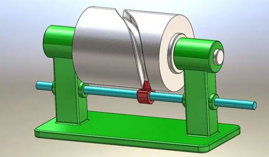
1.5.3 Cylindrical Cam Indexing Mechanism
As shown in Figure 1-3, the cylindrical cam indexing mechanism has a cylindrical drive component. The follower disc has several rollers evenly distributed along the turntable’s circumference, with their axes parallel to the turntable’s axis, and the cam and turntable axes intersect perpendicularly. When the rollers rotate, the cam profile pushes them to achieve indexing, and during the dwell phase, two adjacent rollers clamp the cam’s annular ridge, stopping the turntable. This mechanism ensures good positioning without additional devices.
The rollers can be cylindrical or conical, with wear distributed across several contact points with the cam. To eliminate wear, the roller disc should allow axial adjustment to maintain uniform axial positions. If axial alignment is ensured, angular wear can be compensated by adjusting the disc’s angular position.
Design and Analysis
To analyze the cylindrical cam indexing mechanism, kinematic and dynamic analyses are essential. These analyses determine the cam profile’s geometry, follower displacement, velocity, and acceleration profiles, ensuring smooth operation and precise indexing. Furthermore, a stress analysis of the cam and followers helps identify potential wear and failure points, enhancing the mechanism’s longevity and reliability.
Using software tools such as SolidWorks for 3D modeling and MATLAB for dynamic simulation aids in visualizing and validating the design. These tools help iterate the design process efficiently, ensuring the final mechanism meets the required performance specifications.
In conclusion, cam-driven indexing mechanisms, particularly cylindrical cam indexing mechanisms, are vital in modern automated machinery. Their precise and reliable operation enhances production efficiency and accuracy, making them indispensable in various industries.
Maximize Tooling and CNC Metal Spinning Capabilities.

At BE-CU China Metal Spinning company, we make the most of our equipment while monitoring signs of excess wear and stress. In addition, we look into newer, modern equipment and invest in those that can support or increase our manufacturing capabilities. Our team is very mindful of our machines and tools, so we also routinely maintain them to ensure they don’t negatively impact your part’s quality and productivity.
Talk to us today about making a rapid prototype with our CNC metal spinning service. Get a direct quote by chatting with us here or request a free project review.
BE-CU China CNC Metal Spinning service include : CNC Metal Spinning,Metal Spinning Die,Laser Cutting, Tank Heads Spinning,Metal Hemispheres Spinning,Metal Cones Spinning,Metal Dish-Shaped Spinning,Metal Trumpet Spinning,Metal Venturi Spinning,Aluminum Spinning Products,Stainless Steel Spinning Products,Copper Spinning Products,Brass Spinning Products,Steel Spinning Product,Metal Spinnin LED Reflector,Metal Spinning Pressure Vessel,