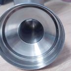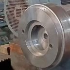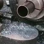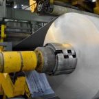
Spinning is a process method that uses a tool to continuously apply pressure to a very small part of the workpiece to gradually shape it. Spinning deformation is a local progressive deformation, and its progressiveness is similar to swing rolling. According to the deformation characteristics of spinning, the spinning process can be divided into two categories: ordinary spinning and high-power spinning [1]. Using software to simulate the high-power spinning process can clearly obtain the required data and effectively prevent defects in actual production.
Software modeling and simulation
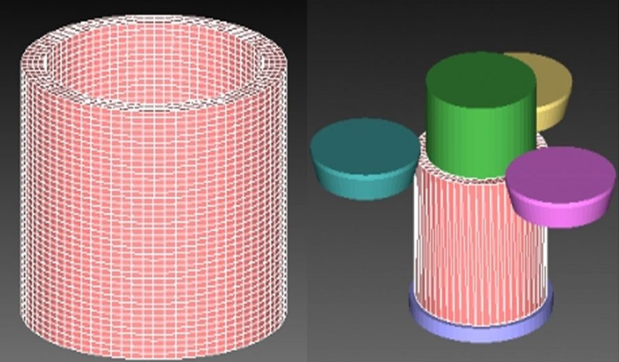
In this paper, the metal forming software Simufact is used to simulate the high-power spinning process. The simulation process ignores the influence of gravity and metal inclusions, and ignores the influence of temperature changes on the workpiece during the spinning process. The workpiece material is DB.DIN-1.7242-w alloy steel. The wheel, baffle, and spindle are defined as rigid bodies, and the baffle and the blank are fixedly connected. A hexahedral grid is selected, and the number of grids is about 10,000, as shown in Figure 1. The established high-power spinning model is shown in Figure 2. Figure 1 Workpiece mesh division Figure 2 Power spinning geometric model The blank length, wall thickness, and inner diameter are =50mm, =2mm, and =50mm respectively; spindle diameter = 49.95mm, wheel diameter = 50mm, feed ratio = 0.6mm/r, and wheel working angle α = 20°. Table 1 Some spinning process parameters
| Parameter Symbol Assigned value |
| Spindle speed (r/min) n 100 |
| Spinning temperature /℃ T 20 |
| Thinning rate /% 30, 40, 50 |
Relationship between the force and thinning rate of the high-force spinning wheel of cylindrical parts
When simulating with different thinning rates, the pressure on each wheel is also different, and the simulated force data is shown in Figure 3. T / secFigure 3 Schematic diagram of the force on the wheel during the simulation Its data conforms to the normal distribution. The force on the wheel is taken at 6 time points.
The specific situation is shown in Figures 4 to 6. T/secWheel 1 is subjected to force in the XY plane Wheel 2 is subjected to force in the XY plane Wheel 3 is subjected to force 4 =30% of the force on each wheelT /secWheel 1 is subjected to force in the XY plane Wheel 2 is subjected to force in the XY plane Wheel 3 is subjected to force in the XY plane Figure 5 =40% of the force on each wheelT /secWheel 1 is subjected to force in the XY plane Wheel 2 is subjected to force in the XY plane Wheel 3 is subjected to force in the XY plane Figure 6 =50% of the force on each wheel
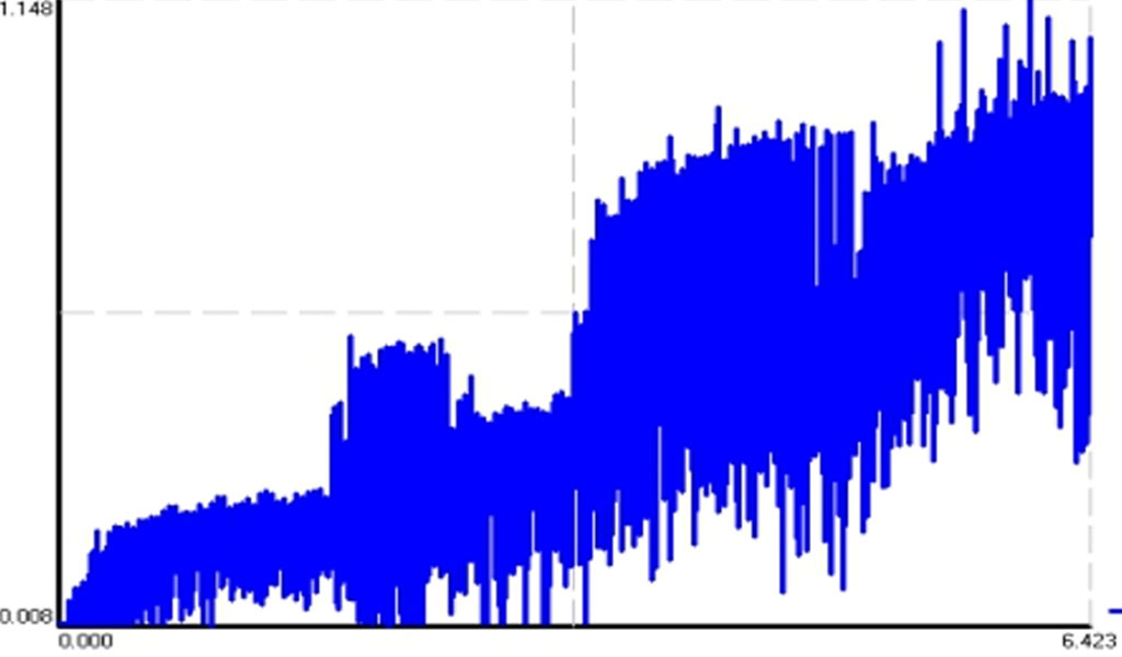

Table 2 Different thinning rates and forces on the rotating wheel in each simulation
| Thinning rate (%) | Force and mean square error of the rotating wheel | ||||
| Rotary wheel 1 | Spinning Wheel 2 | Spin Wheel 3 | Mean square error | ||
| Simulation 1 | 30 | 2.4 | 2.4 | 2.5 | 0.002 |
| Simulation 2 | 40 | 3.5 | 3.5 | 3.7 | 0.009 |
| Simulation 3 | 50 | 5.4 | 5.3 | 5.5 | 0.007 |
As can be seen from Figures 4 to 6 and Table 2, as the thinning rate increases, the force on the spinning wheel increases continuously. When three spinning wheels are used, each spinning wheel will be subjected to forces in the X and Y directions. This simulation has synthesized a force, and the direction is from the center of the core mold to the spinning wheel. Since the thinning rate of each spinning wheel is the same and they are in contact with the leather material at the same time, the force on each spinning wheel is relatively even in the same simulation, which can ensure the straightness of the generatrix of the workpiece and is not prone to elliptical mouths [2]. The magnitude of the force on the spinning wheel is also related to the friction coefficient set in the simulation. As the friction force increases, the force on the spinning wheel also increases [3].
Conclusions
This paper uses the metal forming software Simufact to numerically simulate the high-power spinning process. The magnitude and direction of the force on the spinning wheel at different thinning rates at a given spinning wheel working angle during the spinning process are obtained. The reasons for the generation of different forces are analyzed, accurate data are obtained, and a correction method for eliminating generatrix distortion and elliptical mouths during the spinning process is proposed. The conclusions drawn have certain guiding significance for the optimization of process parameters of high-pressure spinning of cylindrical parts.
Maximize Tooling and CNC Metal Spinning Capabilities.
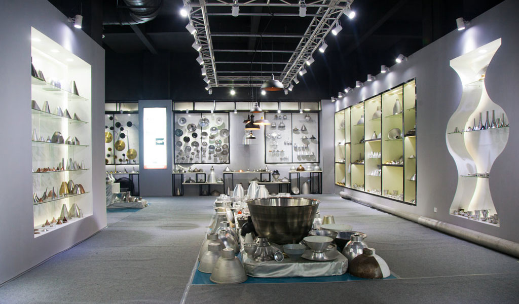
At BE-CU China Metal Spinning company, we make the most of our equipment while monitoring signs of excess wear and stress. In addition, we look into newer, modern equipment and invest in those that can support or increase our manufacturing capabilities. Our team is very mindful of our machines and tools, so we also routinely maintain them to ensure they don’t negatively impact your part’s quality and productivity.
Talk to us today about making a rapid prototype with our CNC metal spinning service. Get a direct quote by chatting with us here or request a free project review.
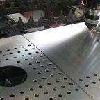
BE-CU China CNC Metal Spinning service include : CNC Metal Spinning,Metal Spinning Die,Laser Cutting, Tank Heads Spinning,Metal Hemispheres Spinning,Metal Cones Spinning,Metal Dish-Shaped Spinning,Metal Trumpet Spinning,Metal Venturi Spinning,Aluminum Spinning Products,Stainless Steel Spinning Products,Copper Spinning Products,Brass Spinning Products,Steel Spinning Product,Metal Spinnin LED Reflector,Metal Spinning Pressure Vessel,
