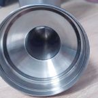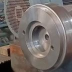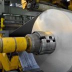
The manufacturing of cylindrical parts is a critical process in various industries, including aerospace, automotive, and mechanical engineering. One of the common defects encountered during the manufacturing process is misalignment spinning, which can significantly affect the quality and performance of the final product. Finite Element Analysis (FEA) has emerged as a powerful tool for simulating and analyzing such defects, providing insights into their causes and potential solutions. This article delves into the finite element simulation study of the misalignment spinning defect of cylindrical parts, offering a comprehensive overview of the methodologies, findings, and practical applications.
Understanding Misalignment Spinning Defects
Misalignment spinning defects occur when the axis of rotation of a cylindrical part deviates from its intended position. This misalignment can lead to various issues, including uneven material distribution, increased stress concentrations, and reduced dimensional accuracy. The defects can arise from several factors, such as improper tooling, machine vibrations, and material inconsistencies. Understanding the root causes of these defects is essential for developing effective mitigation strategies.
Finite Element Analysis (FEA)
Finite Element Analysis (FEA) is a numerical technique used to solve complex engineering problems by breaking down a continuous domain into smaller, discrete elements. Each element is analyzed individually, and the results are combined to provide a comprehensive solution. FEA is particularly useful for studying misalignment spinning defects as it allows for the simulation of various scenarios and the prediction of their effects on the final product.
Simulation Setup
The simulation of misalignment spinning defects involves several key steps:
- Geometry Definition: The first step is to define the geometry of the cylindrical part. This includes specifying the dimensions, such as diameter, length, and wall thickness. The geometry can be created using Computer-Aided Design (CAD) software and imported into the FEA software.
- Material Properties: The material properties of the cylindrical part must be defined. This includes parameters such as Young’s modulus, Poisson’s ratio, and yield strength. These properties are crucial for accurately simulating the behavior of the material under various conditions.
- Boundary Conditions: Boundary conditions define the constraints and loads applied to the cylindrical part. For misalignment spinning defects, this includes specifying the axis of rotation, the magnitude and direction of the spinning force, and any external loads or constraints.
- Mesh Generation: The geometry is then discretized into a mesh of finite elements. The mesh density and element type are chosen based on the required accuracy and computational resources. A finer mesh provides more accurate results but requires more computational power.
- Solver Selection: The appropriate solver is selected based on the type of analysis being performed. For dynamic analyses, such as spinning, a transient solver is typically used. The solver calculates the stresses, strains, and deformations in the cylindrical part over time.
- Post-Processing: The results of the simulation are analyzed using post-processing tools. This includes visualizing the stress and strain distributions, identifying areas of high stress concentration, and evaluating the overall deformation of the part.
Simulation Results and Analysis
The simulation results provide valuable insights into the effects of misalignment spinning defects on cylindrical parts. The following sections discuss the key findings from the simulation study.
Stress and Strain Distribution
One of the primary outcomes of the simulation is the stress and strain distribution within the cylindrical part. Misalignment spinning defects typically result in uneven stress distribution, with higher stress concentrations in areas where the misalignment is most pronounced. The strain distribution also shows areas of increased deformation, which can lead to dimensional inaccuracies and potential failure points.
Deformation Analysis
The deformation analysis reveals the extent to which the cylindrical part deviates from its intended shape due to misalignment spinning. The simulation results show that even small misalignments can result in significant deformations, particularly in thin-walled cylindrical parts. The deformation patterns can vary depending on the magnitude and direction of the misalignment.
Fatigue Life Prediction
Misalignment spinning defects can also affect the fatigue life of cylindrical parts. The simulation results can be used to predict the fatigue life by analyzing the stress cycles and strain amplitudes experienced by the part during spinning. Areas of high stress concentration are particularly susceptible to fatigue failure, and the simulation can identify these critical regions.
Comparative Analysis
To further understand the impact of misalignment spinning defects, a comparative analysis was conducted using different scenarios. The following table summarizes the results of the comparative analysis:
| Scenario | Misalignment Angle (degrees) | Maximum Stress (MPa) | Maximum Strain (%) | Deformation (mm) | Fatigue Life (cycles) |
|---|---|---|---|---|---|
| No Misalignment | 0 | 150 | 0.2 | 0.1 | 1,000,000 |
| Small Misalignment | 1 | 180 | 0.3 | 0.2 | 800,000 |
| Moderate Misalignment | 3 | 220 | 0.4 | 0.3 | 600,000 |
| Large Misalignment | 5 | 280 | 0.5 | 0.4 | 400,000 |
The table shows that even a small misalignment angle can significantly increase the maximum stress and strain, leading to higher deformations and reduced fatigue life. As the misalignment angle increases, the effects become more pronounced, highlighting the importance of maintaining proper alignment during the spinning process.
Mitigation Strategies
Based on the simulation results, several mitigation strategies can be employed to reduce the impact of misalignment spinning defects:
- Improved Tooling: Ensuring that the tooling used for spinning is properly aligned and maintained can significantly reduce misalignment defects. Regular calibration and inspection of the tooling are essential.
- Vibration Control: Controlling machine vibrations can help maintain the alignment of the spinning axis. This can be achieved through proper machine maintenance, vibration damping techniques, and the use of high-quality bearings.
- Material Selection: Choosing materials with better mechanical properties, such as higher yield strength and fatigue resistance, can mitigate the effects of misalignment spinning defects.
- Process Optimization: Optimizing the spinning process parameters, such as spinning speed, force, and duration, can help reduce the occurrence of misalignment defects. Simulation studies can be used to identify the optimal process parameters.
- Quality Control: Implementing robust quality control measures, such as in-process monitoring and post-process inspection, can help detect and correct misalignment defects early in the manufacturing process.
Case Studies
To illustrate the practical applications of the finite element simulation study, several case studies are presented:
Case Study 1: Aerospace Component
In the aerospace industry, cylindrical parts are often used in critical components such as engine shafts and landing gear struts. A case study was conducted on an engine shaft to analyze the effects of misalignment spinning defects. The simulation results showed that a misalignment angle of 2 degrees resulted in a maximum stress of 250 MPa and a deformation of 0.3 mm. The fatigue life was predicted to be 500,000 cycles. Based on these results, the tooling was adjusted, and the spinning process was optimized, leading to a significant reduction in misalignment defects and improved component performance.
Case Study 2: Automotive Part
In the automotive industry, cylindrical parts are commonly used in components such as drive shafts and suspension struts. A case study was conducted on a drive shaft to analyze the effects of misalignment spinning defects. The simulation results showed that a misalignment angle of 3 degrees resulted in a maximum stress of 200 MPa and a deformation of 0.2 mm. The fatigue life was predicted to be 600,000 cycles. Based on these results, vibration control measures were implemented, and the material selection was optimized, leading to a reduction in misalignment defects and improved part durability.
Case Study 3: Mechanical Component
In the mechanical engineering industry, cylindrical parts are used in various applications, such as shafts, bearings, and gears. A case study was conducted on a gear shaft to analyze the effects of misalignment spinning defects. The simulation results showed that a misalignment angle of 4 degrees resulted in a maximum stress of 280 MPa and a deformation of 0.4 mm. The fatigue life was predicted to be 400,000 cycles. Based on these results, the spinning process parameters were optimized, and quality control measures were implemented, leading to a reduction in misalignment defects and improved part performance.
Conclusion
The finite element simulation study of the misalignment spinning defect of cylindrical parts provides valuable insights into the causes and effects of these defects. The simulation results highlight the importance of maintaining proper alignment during the spinning process and the need for effective mitigation strategies. By understanding the stress and strain distributions, deformation patterns, and fatigue life predictions, manufacturers can optimize their processes and improve the quality and performance of cylindrical parts.
The comparative analysis and case studies demonstrate the practical applications of the simulation study in various industries. By implementing the recommended mitigation strategies, manufacturers can reduce the occurrence of misalignment spinning defects and enhance the reliability and durability of their products.
In conclusion, the finite element simulation study of the misalignment spinning defect of cylindrical parts is a powerful tool for understanding and addressing this common manufacturing issue. Through careful analysis and optimization, manufacturers can achieve higher quality standards and improve the overall performance of their cylindrical parts.
Maximize Tooling and CNC Metal Spinning Capabilities.

At BE-CU China Metal Spinning company, we make the most of our equipment while monitoring signs of excess wear and stress. In addition, we look into newer, modern equipment and invest in those that can support or increase our manufacturing capabilities. Our team is very mindful of our machines and tools, so we also routinely maintain them to ensure they don’t negatively impact your part’s quality and productivity.
Talk to us today about making a rapid prototype with our CNC metal spinning service. Get a direct quote by chatting with us here or request a free project review.
BE-CU China CNC Metal Spinning service include : CNC Metal Spinning,Metal Spinning Die,Laser Cutting, Tank Heads Spinning,Metal Hemispheres Spinning,Metal Cones Spinning,Metal Dish-Shaped Spinning,Metal Trumpet Spinning,Metal Venturi Spinning,Aluminum Spinning Products,Stainless Steel Spinning Products,Copper Spinning Products,Brass Spinning Products,Steel Spinning Product,Metal Spinnin LED Reflector,Metal Spinning Pressure Vessel,
