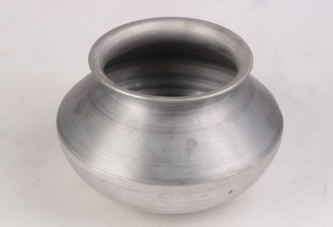
Metal spinning, also known as spin forming or metal turning, is a metalworking process that transforms a flat metal disc or tube into axially symmetric components by rotating it at high speeds while applying localized pressure. This technique is widely used to produce shapes such as cones, cylinders, hemispheres, and hemi-ellipsoids, which are essential in industries like aerospace, automotive, and manufacturing. The mandrel-free metal spinning process, a modern advancement, eliminates the need for a solid mandrel, reducing tooling costs, lead times, and material usage while increasing flexibility in forming complex geometries. This article explores the mandrel-free metal spinning process specifically for forming hemispherical and hemi-ellipsoidal parts from low carbon steel sheets, delving into its principles, mechanics, process parameters, material behavior, and applications. The focus is on low carbon steel due to its favorable ductility, cost-effectiveness, and widespread use in industrial applications. The article also examines experimental and numerical studies, challenges, and future directions, supported by detailed comparative tables.
Historical Context of Metal Spinning
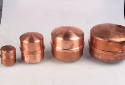
Metal spinning traces its origins to ancient civilizations, with evidence of its use in Ancient Egypt for shaping soft metals like gold and silver into decorative and functional items such as bowls and vases. These early applications relied on manual techniques and human-powered lathes, limiting the process to soft, ductile materials. The Industrial Revolution in the 19th century marked a significant advancement, with steam and hydro power enabling the spinning of harder metals like brass and copper. By the early 20th century, the advent of electric motors and high-speed lathes expanded the process’s capabilities, allowing for the spinning of stainless steel, aluminum, and low carbon steel. The introduction of computer numerical control (CNC) in the late 20th century revolutionized metal spinning, enabling precise control over toolpaths and the ability to form complex geometries, including non-axisymmetric shapes. The development of mandrel-free spinning, pioneered by researchers like Professor Julian Allwood and Omer Music, further enhanced the process’s flexibility by eliminating the need for dedicated tooling, making it more economical and adaptable for low-volume production.
The mandrel-free approach, first demonstrated in academic literature around the early 2010s, represents a paradigm shift in metal spinning. By using numerically controlled rollers instead of a mandrel, this method allows for the forming of both axisymmetric and asymmetric parts with reduced setup costs. For hemispherical and hemi-ellipsoidal parts, which are critical in applications like pressure vessels, satellite domes, and automotive components, mandrel-free spinning offers significant advantages in terms of material efficiency and process flexibility. Low carbon steel, particularly extra deep drawing (EDD) grades with aluminum-killed compositions, has emerged as a preferred material due to its excellent formability and cost-effectiveness, making it ideal for studying the mandrel-free spinning process.
Principles of Mandrel-Free Metal Spinning
Process Mechanics
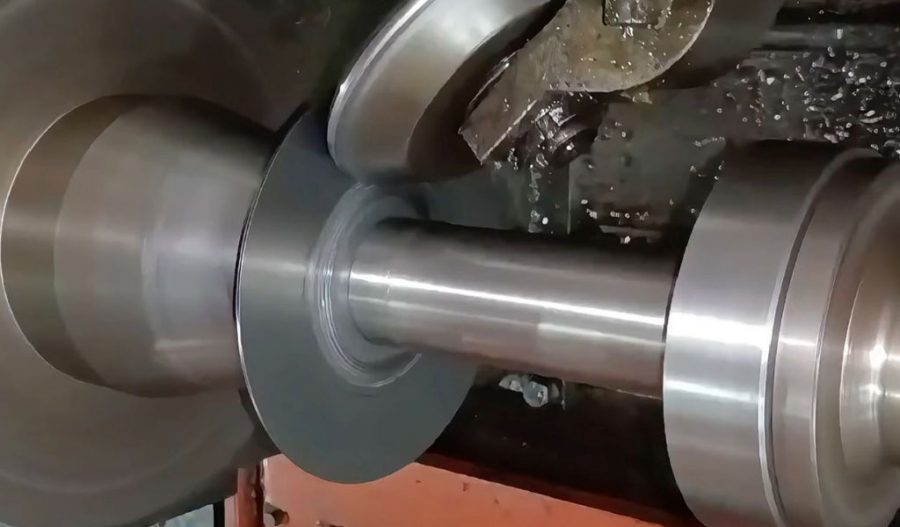
Mandrel-free metal spinning involves clamping a flat sheet metal blank, typically circular, onto a rotating spindle. Unlike conventional spinning, which uses a mandrel to define the final shape, the mandrel-free process relies on a set of computer-controlled rollers to progressively deform the blank into the desired geometry. The deformation occurs through localized plastic deformation as the roller applies force against the rotating blank, causing it to flow and conform to the programmed toolpath. For hemispherical parts, the toolpath is designed to create a uniform radius of curvature, while hemi-ellipsoidal parts require varying curvatures along the major and minor axes, demanding precise control over roller movement.
The process is incremental, meaning the deformation occurs in multiple passes, with each pass incrementally shaping the blank. The rollers, typically made of hardened steel or carbide for durability, vary in diameter and thickness depending on the desired surface finish and radius of curvature. A wider roller produces a smoother surface, while a thinner roller is used for smaller radii. The absence of a mandrel reduces the forces exerted on the tooling, allowing for the use of simpler, less robust equipment compared to conventional spinning. However, this also introduces challenges in controlling wrinkling and thickness variations, which are critical for achieving defect-free parts.
Material Considerations
Low carbon steel, specifically extra deep drawing (EDD) grades with aluminum-killed compositions, is widely used in mandrel-free spinning due to its high ductility and low strain-hardening characteristics. These properties allow the material to undergo significant plastic deformation without cracking or excessive thinning. The typical thickness of low carbon steel sheets used in this process ranges from 1.0 to 2.0 mm, with 1.6 mm being a common choice for experimental studies due to its balance of formability and structural integrity. The chemical composition of EDD low carbon steel typically includes 0.08–0.12% carbon, 0.4–0.5% manganese, and trace amounts of aluminum for grain refinement, ensuring a fine, uniform microstructure that enhances formability.
The mechanical properties of low carbon steel, such as a yield strength of approximately 150–200 MPa and an ultimate tensile strength of 300–350 MPa, make it suitable for spinning applications. Its elongation at break, often exceeding 40%, allows for significant stretching and bending during forming. The material’s normal anisotropy (r̄), which measures its ability to deform preferentially in the thickness direction, is typically high (1.5–2.0), further enhancing its suitability for deep drawing and spinning processes. However, the material’s response to high strain rates and localized deformation in mandrel-free spinning requires careful consideration of process parameters to avoid defects like wrinkling, tearing, or excessive thinning.
Toolpath Generation
Toolpath generation is a critical aspect of mandrel-free spinning, as it determines the accuracy and quality of the final part. In conventional spinning, the mandrel defines the shape, simplifying toolpath design. In contrast, mandrel-free spinning requires sophisticated algorithms to compute roller trajectories that achieve the desired geometry without causing defects. Early approaches to toolpath generation relied on analytical models, such as those proposed by Nzahumunyurwa et al. (2001), which computed optimal paths based on material properties and part geometry. However, these models often made simplifying assumptions that limited their applicability to complex shapes like hemi-ellipsoids.
Modern toolpath generation leverages CNC technology and finite element analysis (FEA) to simulate the deformation process and optimize roller trajectories. Statistical techniques, such as the design of experiments (DOE) approach used by Auer et al. (2004), have been employed to derive toolpaths based on empirical data from previously formed parts. More recent advancements include closed-loop control systems that use integrated force sensors to adjust roller trajectories in real-time, ensuring consistent forming forces and minimizing defects. For hemispherical parts, the toolpath typically involves a series of radial passes that gradually reduce the blank’s diameter, while hemi-ellipsoidal parts require elliptical or multi-axis paths to account for varying curvatures.
Experimental Studies
Methodology
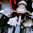
Experimental studies on mandrel-free spinning of low carbon steel sheets typically involve a CNC spinning lathe equipped with numerically controlled rollers. The setup includes a spindle to rotate the blank, a clamping mechanism to secure it, and a roller assembly mounted on a multi-axis arm. The blank, usually a circular disc of 1.6 mm thick EDD low carbon steel, is lubricated with grease or wax to reduce friction and enhance surface finish. The spinning process is conducted at room temperature to avoid thermal effects on material properties, although hot spinning may be used for thicker or less ductile materials.
Key process parameters include the spindle speed (typically 200–1000 RPM), roller feed rate (0.5–5 mm/rev), radial feed rate (1–10 mm/pass), and roller geometry (diameter and thickness). These parameters are varied systematically to study their effects on part quality, thickness distribution, hardness, microstructure, surface roughness, and forming limit diagrams (FLDs). The experiments often involve multiple passes, with intermediate measurements to track the evolution of deformation. For hemispherical parts, the target shape is a dome with a uniform radius, while hemi-ellipsoidal parts aim for an elliptical cross-section with defined major and minor axes.
Results and Analysis
A seminal study by Arunkumar and Chandramohan (2019) investigated the mandrel-free spinning of 1.6 mm thick low carbon steel sheets into hemispherical and hemi-ellipsoidal parts. The study reported successful forming of defect-free parts with minimal thickness variation (less than 10%) and improved hardness due to strain hardening. The thickness distribution showed a slight reduction near the pole of the hemisphere, attributed to higher stretching, while the hemi-ellipsoidal parts exhibited more uniform thinning due to the varying curvature. The hardness increased by 20–30% in the deformed regions, reflecting the material’s work-hardening behavior.
Microstructural analysis revealed elongation of grains in the direction of deformation, with a finer grain structure near the surface due to higher shear strains. Surface roughness measurements indicated a smoother finish (Ra < 1.5 μm) in regions contacted by wider rollers, while narrower rollers produced slightly rougher surfaces (Ra ≈ 2.0 μm). The forming limit diagram (FLD) showed that the material remained within safe strain limits, with major strains below 0.4 and minor strains near zero, indicating near-plane strain conditions. Wrinkling was observed at higher feed rates (>5 mm/rev), highlighting the importance of optimizing process parameters.
Comparative experiments with conventional spinning (using a mandrel) demonstrated that mandrel-free spinning achieved comparable shape accuracy but with reduced tooling costs and setup times. However, the absence of a mandrel increased the risk of wrinkling, particularly for hemi-ellipsoidal parts with complex curvatures. The study concluded that mandrel-free spinning is viable for low-volume production of hemispherical and hemi-ellipsoidal parts, provided toolpaths and process parameters are carefully optimized.
Comparative Table: Mandrel-Free vs. Conventional Spinning
| Parameter | Mandrel-Free Spinning | Conventional Spinning |
|---|---|---|
| Tooling Cost | Low (no mandrel required) | High (precision mandrel needed) |
| Setup Time | Short (minimal tooling preparation) | Long (mandrel design and fabrication) |
| Material Efficiency | High (no mandrel material waste) | Moderate (mandrel material cost) |
| Shape Flexibility | High (axisymmetric and asymmetric shapes) | Limited (primarily axisymmetric shapes) |
| Forming Forces | Low (incremental deformation) | Moderate (mandrel constrains deformation) |
| Wrinkling Risk | Higher (no mandrel support) | Lower (mandrel stabilizes blank) |
| Thickness Variation | 5–10% (depends on toolpath) | 3–8% (mandrel ensures uniformity) |
| Surface Finish (Ra, μm) | 1.5–2.0 (roller-dependent) | 1.0–1.5 (mandrel improves finish) |
| Applications | Prototyping, low-volume production | Medium to high-volume production |
Numerical Modeling and Simulation
Finite Element Analysis (FEA)
Finite element analysis (FEA) is widely used to model the mandrel-free spinning process, providing insights into stress distribution, strain paths, and defect formation. FEA models typically represent the blank as a deformable shell or solid element, with the roller modeled as a rigid body. The material model for low carbon steel incorporates isotropic hardening and von Mises yield criteria, with properties derived from tensile tests (e.g., yield strength ≈ 180 MPa, ultimate tensile strength ≈ 320 MPa, elongation ≈ 42%). Friction between the roller and blank is modeled using a Coulomb friction coefficient (μ ≈ 0.1–0.2), adjusted based on lubrication conditions.
A study published in ScienceDirect (Web ID: 3) developed an FEA model to analyze the stress distribution and strain paths in mandrel-free spinning of non-axisymmetric parts. The model showed that the stress distribution differs from conventional spinning, with higher shear stresses near the roller contact zone due to the absence of a mandrel. The strain path indicated a combination of plane strain and biaxial stretching, with wrinkling occurring when the compressive hoop stresses exceeded the material’s buckling limit. Validation against experimental data confirmed the model’s accuracy in predicting forming forces, with errors less than 15%.
For hemispherical parts, FEA simulations predict uniform thinning near the pole and slight thickening near the flange, consistent with experimental observations. Hemi-ellipsoidal parts exhibit more complex strain distributions due to varying curvatures, with higher strains along the major axis. The simulations also highlight the importance of toolpath optimization to minimize wrinkling and ensure uniform thickness. Advanced FEA models incorporate adaptive meshing and explicit time integration to handle large deformations and contact interactions, improving computational efficiency and accuracy.
Comparative Table: FEA Models for Mandrel-Free Spinning
| Model Type | Element Type | Computational Time | Accuracy | Applications |
|---|---|---|---|---|
| Axisymmetric | 2D Axisymmetric | Low (~1–2 hours) | High | Simple hemispherical parts |
| Shell | 3D Shell | Moderate (~4–6 hours) | Moderate | Complex geometries, hemi-ellipsoids |
| Solid | 3D Solid | High (~8–12 hours) | High | Detailed stress/strain analysis |
| Hybrid | Shell + Solid | Very High (~12–24 hours) | Very High | Non-axisymmetric parts, wrinkling |
Process Parameters and Optimization
Key Parameters
The success of mandrel-free spinning depends on optimizing several process parameters, including:
- Spindle Speed: Higher speeds (500–1000 RPM) reduce forming time but increase the risk of wrinkling due to inertial effects. Lower speeds (200–400 RPM) improve control but slow the process.
- Roller Feed Rate: A feed rate of 0.5–2 mm/rev minimizes thickness variation and wrinkling, while higher rates (3–5 mm/rev) increase productivity but compromise quality.
- Radial Feed Rate: A radial feed of 1–5 mm/pass ensures gradual deformation, while higher feeds (5–10 mm/pass) risk tearing or excessive thinning.
- Roller Geometry: Wider rollers (20–50 mm diameter) produce smoother surfaces, while narrower rollers (5–15 mm) are used for tight radii.
- Lubrication: Grease or wax reduces friction, improving surface finish and reducing tool wear.
Optimization Techniques
Optimization of these parameters often involves a combination of experimental trials, statistical methods, and numerical simulations. The design of experiments (DOE) approach, as used by Auer et al. (2004), systematically varies parameters to identify optimal combinations. Response surface methodology (RSM) is another common technique, modeling the relationship between parameters and responses like thickness variation or surface roughness. Machine learning algorithms, such as neural networks, are increasingly used to predict optimal toolpaths based on historical data, reducing trial-and-error in process development.
Closed-loop control systems, incorporating force sensors and real-time feedback, have shown promise in optimizing mandrel-free spinning. Arai (2003) developed a control system that adjusts roller trajectories based on measured forming forces, ensuring consistent deformation and minimizing defects. This approach is particularly effective for hemi-ellipsoidal parts, where varying curvatures require dynamic adjustments to the toolpath.
Material Behavior and Defects
Thickness Variation
Thickness variation is a critical concern in mandrel-free spinning, as it affects the structural integrity of the final part. Experimental studies show that hemispherical parts exhibit thinning near the pole (5–10%) due to biaxial stretching, with slight thickening near the flange due to compressive hoop stresses. Hemi-ellipsoidal parts show more uniform thinning (3–8%) due to the varying curvature, which distributes strains more evenly. FEA simulations confirm these trends, highlighting the importance of toolpath design in controlling thickness distribution.
Wrinkling
Wrinkling is a common defect in mandrel-free spinning, caused by compressive hoop stresses in the unsupported flange. The risk is higher in hemi-ellipsoidal parts due to the complex geometry, which induces non-uniform stresses. Lowering the roller feed rate and using wider rollers can mitigate wrinkling, as can closed-loop control systems that adjust forming forces in real-time. FEA models predict wrinkling when the compressive stress exceeds the material’s buckling limit, providing a tool for process optimization.
Surface Roughness
Surface roughness affects the aesthetic and functional quality of spun parts. Mandrel-free spinning typically achieves a roughness of Ra 1.5–2.0 μm, slightly higher than conventional spinning (Ra 1.0–1.5 μm) due to the absence of a mandrel. Wider rollers and effective lubrication improve surface finish, while high feed rates increase roughness. Post-processing, such as polishing, may be required for applications requiring high aesthetic quality, such as decorative components.
Hardness and Microstructure
The plastic deformation in mandrel-free spinning induces strain hardening, increasing the hardness of low carbon steel by 20–30%. Vickers hardness tests show higher values near the surface, where shear strains are greatest. Microstructural analysis reveals elongated grains in the direction of deformation, with a finer grain structure near the surface due to dynamic recrystallization. These changes enhance the material’s strength but may reduce ductility, requiring careful consideration in applications requiring further forming or fatigue resistance.
Applications
Aerospace
Hemispherical and hemi-ellipsoidal parts are critical in aerospace for components like satellite domes, fuel tanks, and pressure vessels. Mandrel-free spinning is ideal for prototyping and low-volume production, where the high cost of mandrel fabrication is prohibitive. The ability to form seamless parts with high structural integrity makes this process suitable for applications requiring resistance to internal pressure, such as spherical vessels for liquid fuel storage.
Automotive
In the automotive industry, hemispherical parts are used in exhaust systems, fuel tanks, and decorative components like hubcaps. Hemi-ellipsoidal shapes are less common but find applications in specialized components like air intake manifolds. Mandrel-free spinning’s flexibility and low tooling costs make it attractive for producing custom or low-volume parts, particularly for high-performance or luxury vehicles.
Industrial and Consumer Goods
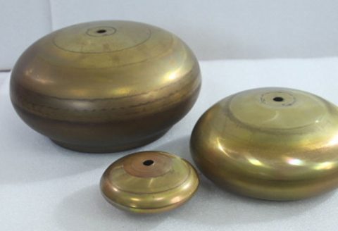
Mandrel-free spinning is used to produce industrial components like pressure vessel heads and consumer goods such as lighting fixtures, cookware, and architectural elements. The process’s ability to create seamless, aesthetically pleasing parts with complex geometries is particularly valuable in decorative applications, where surface finish and shape accuracy are critical.
Comparative Table: Applications of Mandrel-Free Spinning
| Industry | Component | Shape | Advantages | Challenges |
|---|---|---|---|---|
| Aerospace | Satellite domes, fuel tanks | Hemispherical | Seamless, high strength, low tooling cost | Complex toolpath design |
| Automotive | Exhaust components, hubcaps | Hemispherical | Cost-effective for low-volume runs | Surface finish requirements |
| Industrial | Pressure vessel heads | Hemispherical | High material efficiency | Wrinkling risk in large parts |
| Consumer Goods | Lighting fixtures, cookware | Hemi-ellipsoidal | Aesthetic appeal, seamless design | Thickness uniformity |
Challenges and Limitations
Process Control
The absence of a mandrel in mandrel-free spinning increases the complexity of process control, as the blank is unsupported during deformation. This requires precise toolpath design and real-time monitoring to prevent defects like wrinkling or tearing. Closed-loop control systems and advanced sensors are critical for achieving consistent results, but their implementation adds to the process’s complexity and cost.
Material Limitations
While low carbon steel is well-suited for mandrel-free spinning, its formability is limited compared to softer metals like aluminum or copper. Thicker sheets (>2 mm) or high-strength steels may require hot spinning or additional passes, increasing production time and energy consumption. The process is also limited to ductile materials, excluding brittle or low-elongation alloys.
Production Scale
Mandrel-free spinning is best suited for prototyping and low to medium production runs (up to several thousand units). For high-volume production, processes like stamping or deep drawing may be more cost-effective due to faster cycle times and lower labor requirements. The incremental nature of spinning results in longer processing times, typically 2–20 minutes per part, compared to seconds for stamping.
Defect Management
Defects like wrinkling, tearing, or excessive thinning are difficult to repair in spun parts, often requiring the part to be scrapped. This increases material waste and production costs, particularly for complex geometries like hemi-ellipsoids. Advanced process monitoring and optimization techniques are essential for minimizing defects, but they require significant investment in equipment and expertise.
Future Directions
Advanced Toolpath Generation
The development of automated toolpath generation methods, leveraging artificial intelligence (AI) and machine learning, is a promising area of research. These methods can capture the expertise of skilled artisans and generate optimal toolpaths for complex geometries, reducing trial-and-error and improving process efficiency. Recent studies have explored the use of generative adversarial networks (GANs) to predict toolpaths based on part geometry and material properties, with promising results.
Non-Axisymmetric Spinning
While mandrel-free spinning has been successfully applied to axisymmetric parts, its extension to non-axisymmetric shapes, such as elliptical or square parts, is an active area of research. Physical trials have demonstrated the feasibility of asymmetric spinning, but challenges remain in controlling deformation and minimizing defects. Advances in multi-axis CNC machines and real-time control systems are expected to overcome these barriers, expanding the process’s applications.
Sustainable Manufacturing
Mandrel-free spinning’s high material efficiency and low tooling costs align with the principles of sustainable manufacturing. Future research aims to further reduce energy consumption and waste by optimizing process parameters and integrating recycled materials. The use of lightweight, high-strength alloys, such as advanced high-strength steels (AHSS), could enhance the process’s environmental benefits while maintaining performance.
Integration with Additive Manufacturing
The integration of mandrel-free spinning with additive manufacturing (AM) offers exciting possibilities for hybrid manufacturing. AM can be used to create complex blanks or preforms, which are then spun into final shapes using mandrel-free techniques. This approach combines the geometric flexibility of AM with the cost-effectiveness and surface quality of spinning, enabling the production of bespoke components for aerospace and medical applications.
Conclusion
Mandrel-free metal spinning represents a significant advancement in the forming of hemispherical and hemi-ellipsoidal parts from low carbon steel sheets. By eliminating the need for a mandrel, the process reduces tooling costs, setup times, and material waste, making it ideal for prototyping and low-volume production. Its ability to produce seamless, high-strength parts with complex geometries has made it a valuable technique in aerospace, automotive, and industrial applications. However, challenges such as process control, defect management, and production scale limitations require ongoing research and development.
Experimental and numerical studies have provided valuable insights into the process’s mechanics, material behavior, and optimization strategies. Advances in toolpath generation, closed-loop control, and non-axisymmetric spinning are expanding the process’s capabilities, while its alignment with sustainable manufacturing principles positions it as a key technology for the future. As research continues to address current limitations and explore new applications, mandrel-free spinning is poised to play a central role in the evolution of sheet metal forming.
Maximize Tooling and CNC Metal Spinning Capabilities.
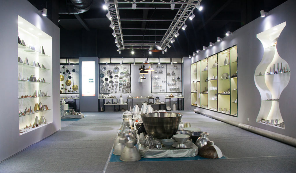
At BE-CU China Metal Spinning company, we make the most of our equipment while monitoring signs of excess wear and stress. In addition, we look into newer, modern equipment and invest in those that can support or increase our manufacturing capabilities. Our team is very mindful of our machines and tools, so we also routinely maintain them to ensure they don’t negatively impact your part’s quality and productivity.
Talk to us today about making a rapid prototype with our CNC metal spinning service. Get a direct quote by chatting with us here or request a free project review.
BE-CU China CNC Metal Spinning service include : CNC Metal Spinning,Metal Spinning Die,Laser Cutting, Tank Heads Spinning,Metal Hemispheres Spinning,Metal Cones Spinning,Metal Dish-Shaped Spinning,Metal Trumpet Spinning,Metal Venturi Spinning,Aluminum Spinning Products,Stainless Steel Spinning Products,Copper Spinning Products,Brass Spinning Products,Steel Spinning Product,Metal Spinnin LED Reflector,Metal Spinning Pressure Vessel,