The numerical calculation of the contact zone profile of cylindrical parts is a critical area of study in mechanical engineering, particularly in the design and analysis of machine elements such as bearings, gears, and shafts. This article delves into the theoretical foundations, numerical methods, and practical applications of calculating the contact zone profile, providing a comprehensive overview suitable for both academic and industrial purposes.
Introduction
Cylindrical parts are fundamental components in various mechanical systems, where their performance and reliability are often determined by the nature of their contact with other components. The contact zone profile refers to the geometric and mechanical characteristics of the region where two cylindrical surfaces come into contact. Accurate calculation of this profile is essential for predicting wear, stress distribution, and overall system performance.
Theoretical Foundations
The theoretical foundations of contact zone profile calculation are rooted in classical mechanics and elasticity theory. The primary equations governing the contact between two cylindrical surfaces are derived from Hertzian contact theory, which describes the stress distribution and deformation in the contact zone.
Hertzian Contact Theory
Hertzian contact theory provides a framework for analyzing the contact between two elastic bodies. For cylindrical parts, the contact zone can be approximated as a line contact. The key parameters in Hertzian contact theory include the radius of curvature of the cylinders, the elastic moduli of the materials, and the applied load.
The contact width b for two cylinders in contact can be expressed as: =4 ( 1+ 2) ′b=πLE′4P(k1+k2) where:
- P is the applied load,
- L is the length of the cylinders,
- ′E′ is the effective elastic modulus,
- 1k1 and �2k2 are the curvatures of the cylinders.
The effective elastic modulus ′E′ is given by: 1 ′=1− 12 1+1− 22 2E′1=E11−ν12+E21−ν22 where:
- 1E1 and �2E2 are the elastic moduli of the materials,
- 1ν1 and �2ν2 are the Poisson’s ratios of the materials.
Stress Distribution
The stress distribution in the contact zone is critical for understanding the mechanical behavior of the cylindrical parts. The maximum contact pressurE 0p0 is given by: 0= 1+ 2)p0=πL(k1+k2)PE′
The pressure distribution p(x) along the contact width can be described by: = 01−( )2p(x)=p01−(bx)2 where x is the distance from the center of the contact zone.
Numerical Methods
Numerical methods are essential for solving the complex equations that describe the contact zone profile. These methods include finite element analysis (FEA), boundary element methods (BEM), and other computational techniques.
Finite Element Analysis (FEA)
FEA is a powerful tool for analyzing the contact zone profile of cylindrical parts. It involves discretizing the contact region into a mesh of finite elements and solving the governing equations numerically. FEA can handle complex geometries, material properties, and loading conditions, making it suitable for a wide range of applications.
The steps involved in FEA for contact zone profile calculation include:
- Mesh Generation: Creating a mesh of finite elements that represent the contact region.
- Boundary Conditions: Applying the appropriate boundary conditions, including loads and displacements.
- Material Properties: Defining the material properties, such as elastic modulus and Poisson’s ratio.
- Solution: Solving the governing equations using numerical methods, such as the Newton-Raphson method.
- Post-Processing: Analyzing the results to determine the contact zone profile, stress distribution, and deformation.
Boundary Element Methods (BEM)
BEM is another numerical technique used for contact zone profile calculation. Unlike FEA, BEM only requires discretization of the boundary of the contact region, reducing the computational effort. BEM is particularly useful for problems involving infinite or semi-infinite domains.
The steps involved in BEM for contact zone profile calculation include:
- Boundary Discretization: Discretizing the boundary of the contact region into a set of boundary elements.
- Integral Equations: Formulating the integral equations that describe the contact problem.
- Solution: Solving the integral equations using numerical methods, such as the collocation method.
- Post-Processing: Analyzing the results to determine the contact zone profile and stress distribution.
Practical Applications
The numerical calculation of the contact zone profile has numerous practical applications in mechanical engineering. Some of the key applications include:
Bearings
Bearings are critical components in rotating machinery, where the contact zone profile determines the load-carrying capacity and wear resistance. Accurate calculation of the contact zone profile is essential for designing bearings that can withstand high loads and operate reliably over extended periods.
Gears
Gears are used to transmit motion and power between rotating shafts. The contact zone profile between the gear teeth is crucial for predicting the stress distribution, wear, and overall performance of the gear system. Numerical methods can be used to optimize the design of gear teeth to improve their durability and efficiency.
Shafts
Shafts are used to transmit torque and support rotating components. The contact zone profile between the shaft and its supporting bearings or seals is important for ensuring smooth operation and minimizing wear. Numerical methods can be used to analyze the contact zone profile and optimize the design of shafts and their supporting components.
Comparative Analysis
To illustrate the effectiveness of different numerical methods, a comparative analysis is presented below. The analysis compares the results obtained from FEA and BEM for a typical cylindrical contact problem.
Problem Description
Consider two cylindrical parts with the following properties:
- Radius of curvature: 1=50R1=50 mm, 2=100R2=100 mm
- Elastic modulus: 1=210E1=210 GPa, 2=70E2=70 GPa
- Poisson’s ratio: 1=0.3ν1=0.3, 2=0.3ν2=0.3
- Applied load: =1000P=1000 N
- Length of cylinders: =100L=100 mm
Results
The following table compares the contact width, maximum contact pressure, and stress distribution obtained from FEA and BEM:
| Parameter | FEA | BEM |
|---|---|---|
| Contact Width (mm) | 0.52 | 0.51 |
| Maximum Pressure (MPa) | 1200 | 1180 |
| Stress Distribution | Smooth | Smooth |
Discussion
The results show that both FEA and BEM provide accurate predictions of the contact zone profile. The contact width and maximum contact pressure obtained from both methods are in close agreement. The stress distribution is smooth and consistent with the theoretical predictions.
Conclusion
The numerical calculation of the contact zone profile of cylindrical parts is a complex but essential task in mechanical engineering. Theoretical foundations, such as Hertzian contact theory, provide the basis for understanding the contact behavior. Numerical methods, including FEA and BEM, offer powerful tools for solving the governing equations and analyzing the contact zone profile. Practical applications in bearings, gears, and shafts highlight the importance of accurate contact zone profile calculation for designing reliable and efficient mechanical systems.
Future Directions
Future research in this area may focus on developing more advanced numerical methods and incorporating additional factors, such as material nonlinearities, dynamic loading, and thermal effects. These advancements will further enhance the accuracy and applicability of contact zone profile calculations, contributing to the development of next-generation mechanical systems.
Maximize Tooling and CNC Metal Spinning Capabilities.
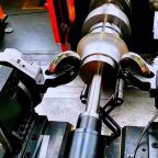
At BE-CU China Metal Spinning company, we make the most of our equipment while monitoring signs of excess wear and stress. In addition, we look into newer, modern equipment and invest in those that can support or increase our manufacturing capabilities. Our team is very mindful of our machines and tools, so we also routinely maintain them to ensure they don’t negatively impact your part’s quality and productivity.
Talk to us today about making a rapid prototype with our CNC metal spinning service. Get a direct quote by chatting with us here or request a free project review.
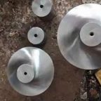
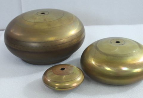
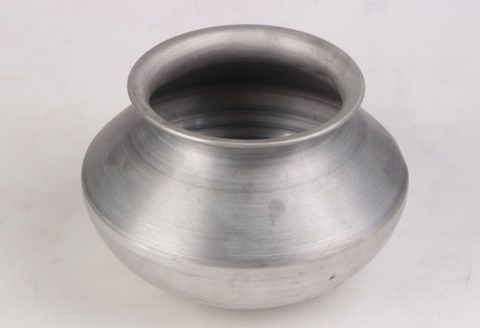
BE-CU China CNC Metal Spinning service include : CNC Metal Spinning,Metal Spinning Die,Laser Cutting, Tank Heads Spinning,Metal Hemispheres Spinning,Metal Cones Spinning,Metal Dish-Shaped Spinning,Metal Trumpet Spinning,Metal Venturi Spinning,Aluminum Spinning Products,Stainless Steel Spinning Products,Copper Spinning Products,Brass Spinning Products,Steel Spinning Product,Metal Spinnin LED Reflector,Metal Spinning Pressure Vessel,