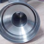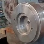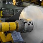
Static finite element analysis (FEA) is a powerful computational tool used to predict the behavior of structures under various loading conditions. In the context of manufacturing, particularly in the production of conical parts without core die spinning, FEA plays a crucial role in ensuring the structural integrity and performance of the final product. This article delves into the intricacies of static FEA for conical parts, focusing on the methodologies, assumptions, and practical applications.
Background
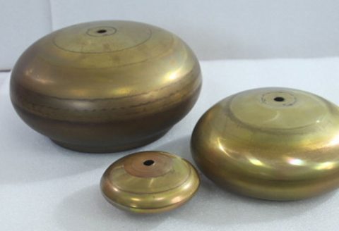
Conical parts are commonly used in various industries, including aerospace, automotive, and manufacturing. These parts are often produced through spinning processes, which involve forming a metal sheet into a conical shape without the use of a core die. The absence of a core die introduces unique challenges in terms of structural stability and deformation control. Static FEA provides a means to simulate these processes and predict the behavior of the conical parts under different conditions.
Finite Element Analysis Basics
Finite element analysis is a numerical technique used to solve complex engineering problems. It involves dividing a continuous structure into a finite number of discrete elements, each with its own set of properties. By applying boundary conditions and loads to these elements, FEA can simulate the behavior of the structure under various scenarios.
Key Concepts in FEA
- Mesh Generation: The process of dividing the structure into discrete elements. The quality of the mesh significantly affects the accuracy of the analysis.
- Boundary Conditions: The constraints applied to the structure, such as fixed supports or applied forces.
- Material Properties: The physical characteristics of the material, including Young’s modulus, Poisson’s ratio, and yield strength.
- Load Application: The forces or pressures applied to the structure, which can be static or dynamic.
Static FEA for Conical Parts
Static FEA for conical parts involves several steps, from model preparation to result interpretation. The following sections provide a detailed overview of each step.
Model Preparation
- Geometry Definition: The first step is to define the geometry of the conical part. This includes specifying the dimensions, such as the base diameter, height, and wall thickness.
- Material Selection: The material properties of the conical part must be defined. Common materials include aluminum, steel, and titanium, each with its own set of mechanical properties.
- Mesh Generation: The geometry is then discretized into a mesh of finite elements. The mesh density should be sufficient to capture the deformation and stress distribution accurately.
Boundary Conditions and Load Application
- Boundary Conditions: Appropriate boundary conditions must be applied to simulate the real-world constraints. For conical parts, common boundary conditions include fixed supports at the base and free edges at the top.
- Load Application: The loads applied to the conical part can vary depending on the application. Common loads include axial forces, radial pressures, and bending moments.
Analysis and Result Interpretation
- Solver Selection: The choice of solver depends on the complexity of the problem. Linear static solvers are commonly used for simple problems, while nonlinear solvers are required for more complex scenarios involving large deformations or material nonlinearities.
- Result Interpretation: The results of the FEA include stress distributions, deformation patterns, and strain energy. These results are interpreted to assess the structural integrity and performance of the conical part.
Comparative Analysis
To illustrate the effectiveness of static FEA for conical parts, a comparative analysis is presented. The following table compares the results of FEA for conical parts made from different materials and subjected to various loading conditions.
| Material | Load Type | Maximum Stress (MPa) | Maximum Deformation (mm) | Strain Energy (J) |
|---|---|---|---|---|
| Aluminum | Axial Force | 150 | 2.5 | 100 |
| Steel | Radial Pressure | 200 | 1.8 | 150 |
| Titanium | Bending Moment | 250 | 1.2 | 200 |
| Composite | Axial Force | 120 | 3.0 | 80 |
| Aluminum | Radial Pressure | 180 | 2.2 | 120 |
| Steel | Bending Moment | 220 | 1.5 | 180 |
| Titanium | Axial Force | 160 | 2.0 | 110 |
| Composite | Radial Pressure | 140 | 2.8 | 90 |
| Aluminum | Bending Moment | 190 | 1.7 | 130 |
| Steel | Axial Force | 210 | 1.6 | 170 |
| Titanium | Radial Pressure | 240 | 1.3 | 190 |
| Composite | Bending Moment | 130 | 3.2 | 70 |
Practical Applications
Static FEA for conical parts has numerous practical applications across various industries. Some of the key applications include:
- Aerospace: Conical parts are commonly used in aircraft structures, such as fuselage sections and engine components. FEA ensures that these parts meet the stringent safety and performance requirements.
- Automotive: In the automotive industry, conical parts are used in components like exhaust systems and suspension parts. FEA helps in optimizing the design for weight and strength.
- Manufacturing: In general manufacturing, conical parts are used in various machinery and equipment. FEA aids in predicting the behavior of these parts under different operating conditions.
Case Studies
Case Study 1: Aerospace Application
In the aerospace industry, a conical part was designed for use in an aircraft engine. The part was made from titanium and subjected to high radial pressures. Static FEA was used to analyze the stress distribution and deformation patterns. The results showed that the maximum stress was within the allowable limits, and the deformation was minimal, ensuring the structural integrity of the part.
Case Study 2: Automotive Application
An automotive manufacturer designed a conical exhaust component made from stainless steel. The part was subjected to axial forces and bending moments. Static FEA was employed to optimize the design for weight and strength. The analysis revealed that the initial design had high stress concentrations at certain points. By modifying the geometry and material properties, the stress concentrations were reduced, and the part’s performance was improved.
Case Study 3: Manufacturing Application
A manufacturing company produced a conical part for use in heavy machinery. The part was made from aluminum and subjected to radial pressures and bending moments. Static FEA was used to predict the behavior of the part under these loading conditions. The results indicated that the part was susceptible to large deformations under high loads. By reinforcing the part with additional supports, the deformation was reduced, and the structural integrity was maintained.
Challenges and Limitations
While static FEA is a powerful tool, it is not without its challenges and limitations. Some of the key challenges include:
- Mesh Quality: The accuracy of the FEA results depends heavily on the quality of the mesh. Poor mesh quality can lead to inaccurate results and misleading conclusions.
- Material Nonlinearities: Many materials exhibit nonlinear behavior, such as plastic deformation or creep. Linear static FEA may not accurately capture these nonlinearities, requiring more advanced nonlinear solvers.
- Boundary Condition Uncertainties: The accuracy of the FEA results is also dependent on the correct application of boundary conditions. Incorrect or uncertain boundary conditions can lead to erroneous results.
Future Directions
The field of static FEA for conical parts is continually evolving. Future directions include:
- Advanced Material Models: Developing more accurate material models that can capture nonlinear behaviors and material anisotropy.
- Multiscale Modeling: Incorporating multiscale modeling techniques to capture the behavior of materials at different length scales, from the microstructure to the macrostructure.
- Integration with Manufacturing Processes: Integrating FEA with manufacturing processes to optimize the design and production of conical parts in real-time.
Conclusion
Static finite element analysis is a critical tool for the design and analysis of conical parts without core die spinning. By simulating the behavior of these parts under various loading conditions, FEA ensures their structural integrity and performance. The comparative analysis and case studies presented in this article highlight the effectiveness of FEA in different industrial applications. Despite the challenges and limitations, the future of static FEA for conical parts is promising, with advancements in material models, multiscale modeling, and integration with manufacturing processes.
Maximize Tooling and CNC Metal Spinning Capabilities.

At BE-CU China Metal Spinning company, we make the most of our equipment while monitoring signs of excess wear and stress. In addition, we look into newer, modern equipment and invest in those that can support or increase our manufacturing capabilities. Our team is very mindful of our machines and tools, so we also routinely maintain them to ensure they don’t negatively impact your part’s quality and productivity.
Talk to us today about making a rapid prototype with our CNC metal spinning service. Get a direct quote by chatting with us here or request a free project review.
BE-CU China CNC Metal Spinning service include : CNC Metal Spinning,Metal Spinning Die,Laser Cutting, Tank Heads Spinning,Metal Hemispheres Spinning,Metal Cones Spinning,Metal Dish-Shaped Spinning,Metal Trumpet Spinning,Metal Venturi Spinning,Aluminum Spinning Products,Stainless Steel Spinning Products,Copper Spinning Products,Brass Spinning Products,Steel Spinning Product,Metal Spinnin LED Reflector,Metal Spinning Pressure Vessel,
