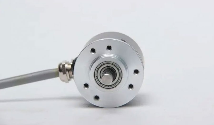
In industrial control systems, devices such as proximity switches and photoelectric switches are commonly used for positioning tasks. With the continuous development of industrial control, rotary encoders have emerged, characterized by:
- Informationization: Besides positioning, the control room can also determine the exact position.
- Flexibility: Positioning can be flexibly adjusted in the control room.
- Ease of Installation and Safety: They are easy to install, safe, and have a long service life.
A rotary encoder can measure distances ranging from a few micrometers to tens or hundreds of meters. Using a single rotary encoder can eliminate the need for multiple proximity switches and photoelectric switches, addressing issues like complicated mechanical installations, susceptibility to damage, and interference from high temperatures and moisture.
Due to the use of an optical code disc, there is no mechanical wear, and as long as the installation is accurate, the encoder’s service life is typically very long.
- Multifunctionality: Besides positioning, they can transmit current positions remotely and calculate motion speeds, which is especially important for applications involving inverters and stepper motors.
- Economical: For multiple control stations, a single rotary encoder can reduce installation, maintenance, and wear costs, while extending service life.
Due to these advantages, rotary encoders are increasingly being applied in various industrial control scenarios.
Definition and Function
An encoder is a device that converts physical signals into signals that can be used for communication, transmission, and storage. It is used as a detection component in speed control or position control systems. An encoder converts angular displacement or linear displacement into electrical signals. The former is known as a code disc, and the latter as a code scale.
Types and Operation
Rotary encoders measure rotational speed and come in single-output and dual-output types. Key technical parameters include pulses per revolution (ranging from a few dozen to several thousand) and supply voltage. Single-output rotary encoders produce a single set of pulses, while dual-output encoders produce two sets of 90-degree phase-shifted pulses. These pulses not only measure rotational speed but also determine the direction of rotation.
Incremental Encoder (Rotary Type) Working Principle:
A center-shafted optical code disc has concentric transparent and opaque lines read by photoelectric emitters and receivers, producing four sinusoidal wave signals (A, B, C, D), each 90 degrees out of phase. By inverting the C and D signals and superimposing them on A and B, stable signals are enhanced. A single Z pulse per revolution represents a zero reference point.
Since the A and B phases are 90 degrees apart, the order in which they occur indicates the encoder’s direction of rotation. The zero pulse provides a zero reference point.
Material of Code Discs:
- Glass: Thin lines on glass offer good thermal stability and high precision.
- Metal: Directly engraved lines are durable but less precise due to metal’s thickness and poorer thermal stability.
- Plastic: Economical with lower cost but less precision, thermal stability, and durability.
Resolution: The number of transparent or opaque lines provided per 360-degree rotation defines the resolution, ranging from 5 to 10,000 lines per revolution.
Signal Output
Output types include sine wave (current or voltage), square wave (TTL, HTL), open collector (PNP, NPN), and push-pull forms. The TTL type uses long-line differential drive (symmetrical A, A-; B, B-; Z, Z-), while HTL is also known as push-pull output. The interface of the signal receiving equipment should match the encoder type.
Signal Connection:
- Encoder pulse signals are typically connected to counters, PLCs, or computers. PLC and computer connections have low-speed and high-speed modules, with varying switch frequencies.
- Single-phase connection: Used for single-direction counting and speed measurement.
- A and B phase connection: Used for bidirectional counting, direction determination, and speed measurement.
- A, B, Z phase connection: Used for position measurement with reference point correction.
- A, A-, B, B-, Z, Z- connection: Symmetrical negative signals contribute zero electromagnetic fields to the cable, minimizing attenuation and providing the best anti-interference capabilities, enabling long-distance transmission.
- For TTL encoders with symmetrical negative signals, the transmission distance can reach 150 meters.
- For HTL encoders with symmetrical negative signals, the transmission distance can reach 300 meters.
Types Based on Reading Method
- Contact Type: Uses brushes to output, with a brush contacting a conductive or insulating area to indicate the state as “1” or “0”.
- Non-contact Type: Uses photosensitive or magnetic elements, where light-sensitive elements represent code states with transparent and opaque areas indicating “1” or “0”.
Types Based on Working Principle
- Incremental Encoders: Convert displacement into periodic electrical signals, then into counting pulses, with the number of pulses indicating displacement.
- Absolute Encoders: Each position corresponds to a unique digital code, so the reading only depends on the start and end positions, not the intermediate process.
Incremental Encoder Applications
Rotary incremental encoders output pulses during rotation, with the position known via counting equipment. If the encoder stops or loses power, position memory relies on the counting equipment’s internal memory. During power interruptions, the encoder must remain immobile to avoid position shift. Position accuracy can be maintained by adding reference points, and operations often start by finding a reference point or zeroing.
For instance, printers and scanners use incremental encoders for positioning, with initial sounds indicating reference point searching.
Absolute Encoder Advantages
Absolute rotary optical encoders provide unique, interference-resistant positions without power loss memory, increasingly used in industrial systems for angle, length measurement, and positioning control.
Resolution and Encoding: Absolute encoders have multiple lines on the optical code disc, arranged in binary (Gray code), providing a unique code for each position. This avoids the need for memory or reference points, significantly improving reliability and anti-interference characteristics.
Single-turn vs. Multi-turn:
- Single-turn Absolute Encoder: Measures within a 360-degree rotation, resetting after a full turn.
- Multi-turn Absolute Encoder: Measures beyond 360 degrees using gear mechanisms to add additional code groups, extending the measurement range and maintaining unique position codes.
Installation and Usage
- High-speed End Installation: Installed on the power motor shaft, offering high resolution. Suitable for high-precision single-direction control (e.g., steel rolling gap control). However, it requires minimal motor vibration to avoid encoder damage.
- Low-speed End Installation: Installed after reduction gears, providing direct, high-precision measurement. Suitable for long-distance positioning (e.g., lifting equipment, feeding car positioning).
- Auxiliary Mechanical Installation: Common methods include gear racks, chain belts, friction wheels, and winding mechanisms.
Optical Encoder Characteristics
- Reflective sensing technology
- Surface mount packaging
- Two-channel analog signal output
- Counting frequency: 20KHz
- Operates on a single 5.0V power supply
- Operating temperature: -10 to 70°C
- Resolution: 180 LPI
- Complies with RoHS environmental standards.
Maximize Tooling and CNC Metal Spinning Capabilities.

At BE-CU China Metal Spinning company, we make the most of our equipment while monitoring signs of excess wear and stress. In addition, we look into newer, modern equipment and invest in those that can support or increase our manufacturing capabilities. Our team is very mindful of our machines and tools, so we also routinely maintain them to ensure they don’t negatively impact your part’s quality and productivity.
Talk to us today about making a rapid prototype with our CNC metal spinning service. Get a direct quote by chatting with us here or request a free project review.
BE-CU China CNC Metal Spinning service include : CNC Metal Spinning,Metal Spinning Die,Laser Cutting, Tank Heads Spinning,Metal Hemispheres Spinning,Metal Cones Spinning,Metal Dish-Shaped Spinning,Metal Trumpet Spinning,Metal Venturi Spinning,Aluminum Spinning Products,Stainless Steel Spinning Products,Copper Spinning Products,Brass Spinning Products,Steel Spinning Product,Metal Spinnin LED Reflector,Metal Spinning Pressure Vessel,
