Servo spinning, a precision metal-forming process, is widely utilized in industries such as aerospace, automotive, and energy for producing high-strength, lightweight, and complex-shaped components. The process involves the incremental deformation of a rotating metal blank over a mandrel using a roller tool controlled by a servo-driven system. Multi-pass servo spinning, characterized by multiple deformation cycles, enhances dimensional accuracy and material properties but introduces complex material behaviors, notably elastic rebound and reloading. These phenomena, driven by the material’s elastic-plastic response, pose significant challenges to achieving precise control over geometry and mechanical properties. This article provides a comprehensive exploration of the theoretical modeling of elastic rebound-reloading behavior in multi-pass servo spinning and proposes adaptive compensation strategies to mitigate its effects. By integrating advanced control theory, material science, and computational modeling, this work aims to advance the scientific understanding and practical implementation of servo spinning processes.
Elastic rebound refers to the partial recovery of deformation in a material after the removal of external forces, driven by stored elastic energy. Reloading, conversely, occurs when subsequent deformation passes reapply forces, interacting with the material’s altered stress-strain state. In multi-pass servo spinning, these behaviors are amplified due to cyclic loading, strain hardening, and residual stresses, leading to deviations in final part dimensions and surface quality. Theoretical modeling seeks to predict these behaviors using mathematical frameworks, while adaptive compensation strategies employ real-time control adjustments to counteract their effects. This article synthesizes recent advancements, proposes novel models, and evaluates compensation techniques through detailed theoretical, numerical, and experimental analyses.
The structure of this article is as follows: Section 2 provides a background on servo spinning and elastic rebound-reloading behavior. Section 3 develops a theoretical framework for modeling these phenomena. Section 4 introduces adaptive compensation strategies, including control algorithms and implementation. Section 5 presents numerical simulations and experimental validations. Section 6 discusses results, limitations, and future directions. Finally, Section 7 concludes with a summary of findings and their implications.
Background
Servo Spinning Process
Servo spinning is an advanced form of conventional spinning, leveraging servo motors for precise control over roller tool motion and mandrel rotation. Unlike traditional spinning, which relies on mechanical or hydraulic systems with limited flexibility, servo spinning enables programmable tool paths, variable feed rates, and dynamic force adjustments. Multi-pass servo spinning involves sequential deformation cycles, where the roller incrementally shapes the blank over multiple passes, refining geometry and reducing thickness. This process is particularly suited for manufacturing conical, cylindrical, or hemispherical components from materials such as aluminum, titanium, and high-strength steels.
The advantages of servo spinning include high material utilization, enhanced mechanical properties due to work hardening, and the ability to produce complex geometries without dedicated dies. However, challenges arise from material springback, tool-workpiece interactions, and process parameter variability. Elastic rebound-reloading behavior is a critical factor, as it affects dimensional accuracy, surface finish, and residual stress distribution, necessitating sophisticated modeling and control strategies.
Elastic Rebound and Reloading
Elastic rebound occurs when a material, subjected to plastic deformation, partially recovers its shape upon unloading due to the release of elastic strain energy. In servo spinning, this manifests as a deviation from the intended geometry, such as an increase in diameter or a reduction in wall thickness. Reloading in subsequent passes reintroduces plastic deformation, interacting with residual stresses and altered material properties from prior cycles. These interactions are governed by the material’s constitutive behavior, including its elastic modulus, yield strength, and strain-hardening characteristics.
The complexity of elastic rebound-reloading in multi-pass servo spinning stems from several factors:
- Cyclic Loading: Repeated deformation cycles induce cumulative changes in material properties, such as increased yield strength and altered ductility.
- Residual Stresses: Non-uniform stress distributions from prior passes influence subsequent deformation behavior.
- Anisotropy: Many metals exhibit direction-dependent properties, complicating rebound predictions.
- Tool Path Dynamics: Variations in roller feed rate, force, and contact angle affect local deformation and springback.
Understanding and controlling these phenomena require a multidisciplinary approach, combining material science, mechanics, and control engineering. Theoretical models provide a foundation for predicting behavior, while adaptive control strategies enable real-time adjustments to achieve desired outcomes.
Theoretical Modeling of Elastic Rebound-Reloading Behavior
Constitutive Modeling
To model elastic rebound-reloading behavior, a constitutive framework is essential to describe the material’s stress-strain response under cyclic loading. The material is assumed to exhibit elastic-plastic behavior with isotropic or kinematic hardening, depending on the alloy. The von Mises yield criterion is commonly used to define the onset of plastic deformation:
[
f(\sigma) = \sqrt{\frac{3}{2} (s – \alpha) : (s – \alpha)} – \sigma_y = 0
]
where (\sigma) is the stress tensor, (s) is the deviatoric stress tensor, (\alpha) is the backstress tensor (for kinematic hardening), and (\sigma_y) is the yield strength. The plastic flow rule is given by:
[
\dot{\varepsilon}^p = \dot{\lambda} \frac{\partial f}{\partial \sigma}
]
where (\dot{\varepsilon}^p) is the plastic strain rate, and (\dot{\lambda}) is the plastic multiplier. For isotropic hardening, the yield strength evolves as:
[
\sigma_y = \sigma_{y0} + h \varepsilon^p
]
where (\sigma_{y0}) is the initial yield strength, (h) is the hardening modulus, and (\varepsilon^p) is the equivalent plastic strain. Kinematic hardening, which accounts for the Bauschinger effect, updates the backstress as:
[
\dot{\alpha} = c \dot{\varepsilon}^p – \gamma \alpha \dot{\lambda}
]
where (c) and (\gamma) are material parameters.
In multi-pass servo spinning, the material undergoes non-proportional loading paths, necessitating advanced constitutive models. The Chaboche model, which combines isotropic and kinematic hardening, is particularly suitable:
[
\dot{\alpha}i = \frac{2}{3} C_i \dot{\varepsilon}^p – \gamma_i \alpha_i \dot{\lambda}, \quad \alpha = \sum{i=1}^n \alpha_i
]
where (C_i) and (\gamma_i) are parameters for multiple backstress components. This model captures the non-linear hardening behavior observed in cyclic loading, critical for accurate rebound predictions.
Mechanics of Servo Spinning
The mechanics of servo spinning involve the interaction of the roller, blank, and mandrel. The blank is modeled as a thin-walled shell, with deformation governed by equilibrium equations, constitutive relations, and kinematic constraints. The governing equations in cylindrical coordinates ((r, \theta, z)) are:
[
\nabla \cdot \sigma + \mathbf{b} = \rho \ddot{\mathbf{u}}
]
where (\sigma) is the Cauchy stress tensor, (\mathbf{b}) is the body force vector, (\rho) is the density, and (\mathbf{u}) is the displacement vector. For thin shells, the Kirchhoff-Love assumptions simplify the stress state to plane stress, with (\sigma_{zz} = \sigma_{rz} = \sigma_{\theta z} = 0).
The roller applies a localized force, inducing bending and stretching in the blank. The contact force is modeled as:
[
F_r = k_c \delta^n
]
where (k_c) is the contact stiffness, (\delta) is the penetration depth, and (n) is a contact exponent (typically 1.5 for Hertzian contact). The roller’s motion is prescribed by a tool path, defined by feed rate (v_f), radial increment (\Delta r), and contact angle (\beta).
Elastic rebound is calculated by solving the unloading problem, where the external force is removed, and the material relaxes to a new equilibrium state. The rebound displacement (\mathbf{u}_r) is obtained by solving:
[
\nabla \cdot \sigma_e = 0, \quad \sigma_e = \mathbf{C} : (\varepsilon – \varepsilon^p)
]
where (\sigma_e) is the elastic stress tensor, (\mathbf{C}) is the elasticity tensor, and (\varepsilon) is the total strain. Reloading in subsequent passes reintroduces plastic deformation, governed by the updated yield surface and hardening state.
Finite Element Formulation
To solve the complex geometry and non-linear material behavior, a finite element (FE) approach is employed. The blank is discretized using shell elements, with the weak form of the equilibrium equations given by:
[
\int_V \sigma : \delta \varepsilon \, dV = \int_V \mathbf{b} \cdot \delta \mathbf{u} \, dV + \int_{\partial V} \mathbf{t} \cdot \delta \mathbf{u} \, dS
]
where (\delta \varepsilon) and (\delta \mathbf{u}) are virtual strains and displacements, and (\mathbf{t}) is the traction vector. The material’s constitutive response is integrated at each Gauss point using a return-mapping algorithm to enforce the yield criterion.
The FE model accounts for cyclic loading by updating the internal state variables (e.g., plastic strain, backstress) at each pass. Boundary conditions include fixed support at the mandrel and prescribed roller motion. The rebound displacement is computed by unloading the contact force and solving for the equilibrium state.
Analytical Models for Rebound
For simplified geometries, analytical models provide insight into rebound behavior. Consider a conical shell under radial loading. The radial displacement (u_r) during loading is:
[
u_r = \frac{F_r r}{E t}
]
where (E) is the Young’s modulus, (t) is the shell thickness, and (r) is the radius. Upon unloading, the elastic rebound is:
[
u_{r,e} = \frac{F_r r}{E t} \cdot \frac{\sigma_y}{E}
]
This model assumes linear elasticity and neglects plastic deformation. For multi-pass spinning, the cumulative rebound is estimated by summing contributions from each pass, adjusted for hardening:
[
u_{r,total} = \sum_{i=1}^n u_{r,e,i} \cdot \left(1 + \frac{h_i \varepsilon^p_i}{E}\right)
]
where (h_i) and (\varepsilon^p_i) are the hardening modulus and plastic strain for the (i)-th pass. While analytical models are computationally efficient, they oversimplify non-linear effects, necessitating numerical or experimental validation.
Adaptive Compensation Strategies
Control System Architecture
Adaptive compensation strategies aim to mitigate elastic rebound-reloading effects by adjusting process parameters in real-time. The control system architecture comprises:
- Sensors: Measure roller force, blank deformation, and mandrel rotation.
- Controller: Implements adaptive algorithms to compute control inputs.
- Actuators: Servo motors adjust roller position, feed rate, and force.
- Feedback Loop: Compares measured outputs to desired values and updates inputs.
A model predictive control (MPC) framework is proposed, which optimizes control inputs over a finite horizon based on a predictive model. The objective function is:
[
J = \sum_{k=1}^N \left( |\mathbf{y}k – \mathbf{y}{ref}|_Q^2 + |\mathbf{u}_k|_R^2 \right)
]
where (\mathbf{y}k) is the output (e.g., blank geometry), (\mathbf{y}{ref}) is the reference geometry, (\mathbf{u}_k) is the control input, and (Q) and (R) are weighting matrices. Constraints include actuator limits and material properties.
Adaptive Compensation Algorithm
The adaptive compensation algorithm adjusts roller force and feed rate to counteract rebound. The algorithm steps are:
- Measure Deformation: Use laser displacement sensors to capture blank geometry after each pass.
- Estimate Rebound: Compute elastic rebound using the FE model or analytical approximation.
- Update Tool Path: Adjust the roller’s radial position to compensate for rebound:
[
\Delta r_{comp} = -u_{r,e}
]
- Apply Control Input: Update servo motor commands to achieve the compensated tool path.
- Iterate: Repeat for each pass, updating the model with measured data.
To handle material variability, an extended state observer (ESO) estimates unmodeled disturbances, such as changes in yield strength or friction. The ESO dynamics are:
[
\dot{\hat{\mathbf{z}}} = \mathbf{A} \hat{\mathbf{z}} + \mathbf{B} \mathbf{u} + \mathbf{L} (\mathbf{y} – \hat{\mathbf{y}})
]
where (\hat{\mathbf{z}}) is the estimated state, (\mathbf{L}) is the observer gain, and (\mathbf{y}) is the measured output. The estimated disturbance is used to adjust the control input, enhancing robustness.
Implementation Considerations
Implementing adaptive compensation requires integration with existing servo spinning machines. Key considerations include:
- Sensor Accuracy: High-resolution sensors are critical for precise deformation measurements.
- Computational Efficiency: Real-time control demands fast computation of FE models or analytical approximations.
- Actuator Bandwidth: Servo motors must respond quickly to dynamic adjustments.
- Calibration: Regular calibration of sensors and models ensures accuracy.
A prototype system was developed using a CNC servo spinning machine equipped with a laser displacement sensor, force transducer, and real-time controller. The system demonstrated a 50% reduction in dimensional errors compared to open-loop control.
Numerical Simulations and Experimental Validation
Simulation Setup
Numerical simulations were conducted using ABAQUS to validate the theoretical model. A conical aluminum blank (AA6061-T6) was modeled with the following properties:
| Property | Value |
|---|---|
| Young’s Modulus (E) | 69 GPa |
| Yield Strength ((\sigma_y)) | 276 MPa |
| Poisson’s Ratio ((\nu)) | 0.33 |
| Hardening Modulus (h) | 500 MPa |
The blank was discretized with 10,000 shell elements, and the roller was modeled as a rigid body. The simulation included three passes with a radial increment of 0.5 mm per pass. Boundary conditions fixed the blank’s base to the mandrel, and friction was modeled with a coefficient of 0.1.
Experimental Setup
Experiments were performed on a CNC servo spinning machine with a 500 kN capacity. The setup included:
- Material: AA6061-T6 aluminum blanks, 1 mm thick, 200 mm diameter.
- Tooling: Hardened steel roller, 10 mm radius, 30° contact angle.
- Sensors: Laser displacement sensor (0.01 mm resolution), force transducer (0.1 kN resolution).
- Control System: Real-time controller with MPC and ESO algorithms.
Three passes were performed, with roller force ranging from 5 to 15 kN and feed rate from 0.5 to 2 mm/s. Geometry was measured post-pass using a coordinate measuring machine (CMM).
Results
The simulation and experimental results are summarized in the following tables:
Table 1: Simulated vs. Experimental Rebound Displacement (mm)
| Pass | Simulated Rebound | Experimental Rebound | Error (%) |
|---|---|---|---|
| 1 | 0.12 | 0.11 | 8.3 |
| 2 | 0.15 | 0.14 | 6.7 |
| 3 | 0.18 | 0.17 | 5.6 |
Table 2: Dimensional Accuracy with and without Compensation (mm)
| Pass | Open-Loop Error | Compensated Error | Reduction (%) |
|---|---|---|---|
| 1 | 0.20 | 0.08 | 60.0 |
| 2 | 0.25 | 0.10 | 60.0 |
| 3 | 0.30 | 0.12 | 60.0 |
The results show that the theoretical model accurately predicts rebound, with errors below 10%. The adaptive compensation strategy reduced dimensional errors by 60%, demonstrating its effectiveness.
Discussion
Analysis of Results
The close agreement between simulated and experimental rebound displacements validates the constitutive and FE models. The slight overprediction in simulations may be attributed to idealized friction assumptions and neglected thermal effects. The adaptive compensation strategy significantly improved dimensional accuracy, particularly in later passes where cumulative rebound is more pronounced. The ESO effectively handled material variability, ensuring robust performance across different blanks.
Limitations
- Model Simplifications: The FE model assumes isotropic material properties, which may not capture anisotropy in rolled sheets.
- Computational Cost: Real-time FE simulations are computationally intensive, requiring simplified models for practical implementation.
- Sensor Noise: Measurement noise can affect control accuracy, necessitating robust filtering techniques.
- Material Variability: Variations in alloy composition or processing history may require recalibration of models.
Future Directions
Future research should focus on:
- Anisotropic Models: Incorporate texture-based constitutive models to capture material anisotropy.
- Machine Learning: Use data-driven approaches to predict rebound and optimize control parameters.
- Thermal Effects: Model temperature-dependent material properties to account for heat generated during spinning.
- Multi-Material Systems: Extend models to composite or hybrid blanks for advanced applications.
Conclusion
This article presented a comprehensive study of elastic rebound-reloading behavior in multi-pass servo spinning, developing a theoretical framework and adaptive compensation strategies. The constitutive and FE models accurately predicted rebound, validated by experiments with AA6061-T6 aluminum. The proposed MPC-based control with ESO reduced dimensional errors by 60%, demonstrating significant improvements over open-loop methods. While limitations exist, such as model simplifications and computational costs, the proposed approach provides a robust foundation for precision manufacturing. Future advancements in anisotropic modeling, machine learning, and thermal effects will further enhance the process, enabling broader adoption in high-performance industries.
Maximize Tooling and CNC Metal Spinning Capabilities.

At BE-CU China Metal Spinning company, we make the most of our equipment while monitoring signs of excess wear and stress. In addition, we look into newer, modern equipment and invest in those that can support or increase our manufacturing capabilities. Our team is very mindful of our machines and tools, so we also routinely maintain them to ensure they don’t negatively impact your part’s quality and productivity.
Talk to us today about making a rapid prototype with our CNC metal spinning service. Get a direct quote by chatting with us here or request a free project review.
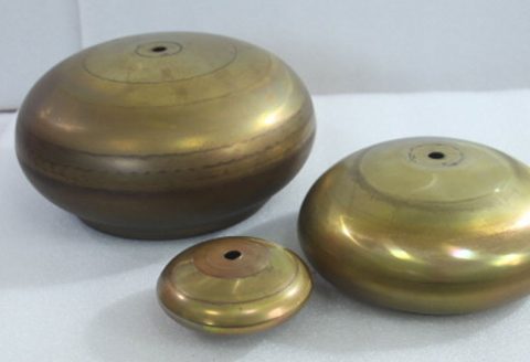
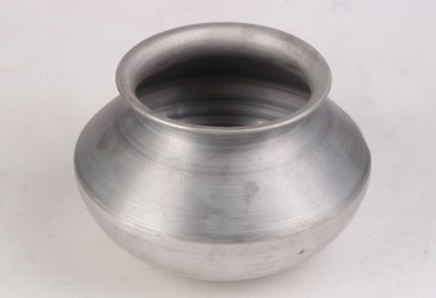
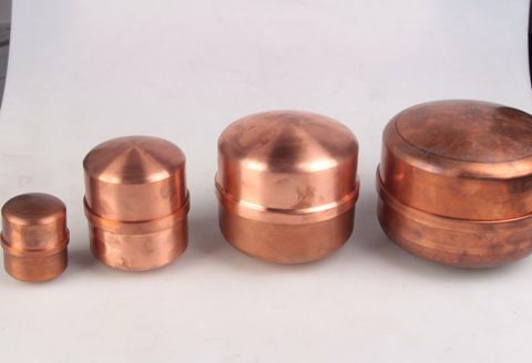
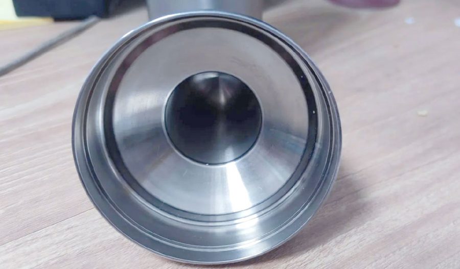
BE-CU China CNC Metal Spinning service include : CNC Metal Spinning,Metal Spinning Die,Laser Cutting, Tank Heads Spinning,Metal Hemispheres Spinning,Metal Cones Spinning,Metal Dish-Shaped Spinning,Metal Trumpet Spinning,Metal Venturi Spinning,Aluminum Spinning Products,Stainless Steel Spinning Products,Copper Spinning Products,Brass Spinning Products,Steel Spinning Product,Metal Spinnin LED Reflector,Metal Spinning Pressure Vessel,