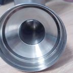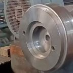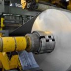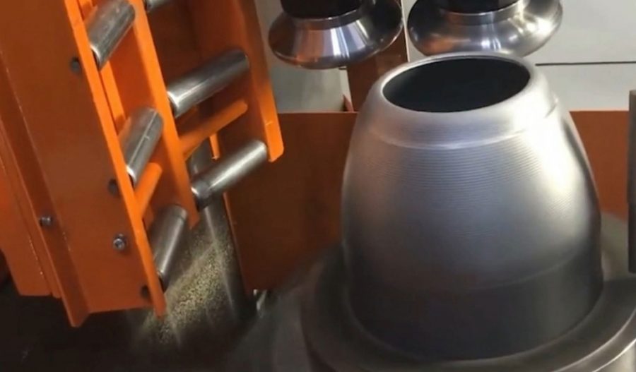
In addition to the three fundamental forming methods previously described, conventional spinning also encompasses various localized forming techniques, such as flanging, curling, lap joining, rib rolling, and trimming, collectively referred to as auxiliary forming processes. These methods aim to achieve the integrity of the finished product. The following sections provide a brief overview of several commonly employed auxiliary forming techniques.
Flanging (Edge Bending) Forming
Flanging is a method wherein the straight outer edge of a workpiece is turned at a specified angle to create a flange or curved edge. This technique is categorized as one of the forms of expansion spinning. There are numerous approaches to flanging, four of which are outlined below:
(1) Single-Wheel Dual-Use Flanging Method
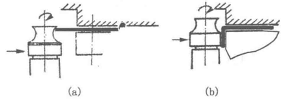
As illustrated in Figure 2-39, this method employs a flanging wheel featuring both an arcuate section and a cylindrical section. Initially, the arcuate segment of the wheel is advanced against the straight outer edge of the workpiece, causing it to curl and transform into an arc (Figure a). Subsequently, the cylindrical section of the wheel flattens the arc against the mold’s end face, resulting in a flange (Figure b). While this method is straightforward, it is best suited for thin-walled workpieces. Performing only the initial operation yields an arced edge.
(2) Dual-Wheel Bending Flanging Method
In Figure 2-40, two forming wheels are depicted: wheel 1, the upper forming wheel, has its working axis perpendicular to the workpiece’s axis and is angled at a small angle β relative to it, without direct contact with the workpiece (wheel 2). Wheel 3, the lower forming wheel, is capable of lateral movement and also possesses a slight tilt. The end face of wheel 3 has a radius r and maintains a specific gap (equal to or slightly greater than the wall thickness of the workpiece) from the working axis of wheel 1. As the workpiece rotates, wheel 3 moves laterally outward at a slow pace, pulling the outer edge of the workpiece to perform a bending deformation and create the flange.
(3) Triple-Wheel Flipping Flanging Method
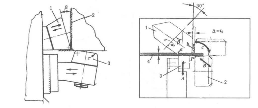
Figure 2-41 illustrates the triple-wheel flanging method, where the axis of the main wheel 1 is inclined at 30° to the vertical and rotates about its own axis. Wheel 3 compresses the workpiece 4 against the edge of wheel 1, enabling rotation (Motion A). The forming wheel 2 flips from its initial position B to an upper position, causing the edge to rotate slowly around point P by 90°, gradually flipping the straight edge of the workpiece into contact with the edge of wheel 1, thereby forming a right-angle flange. The gap Δ between wheels 1 and 2 can be adjusted according to the workpiece’s wall thickness t. This method is highly efficient, capable of flanging workpieces with thicknesses ranging from 2 to 9 millimeters.
(4) Dual-Wheel Flipping Flanging Method
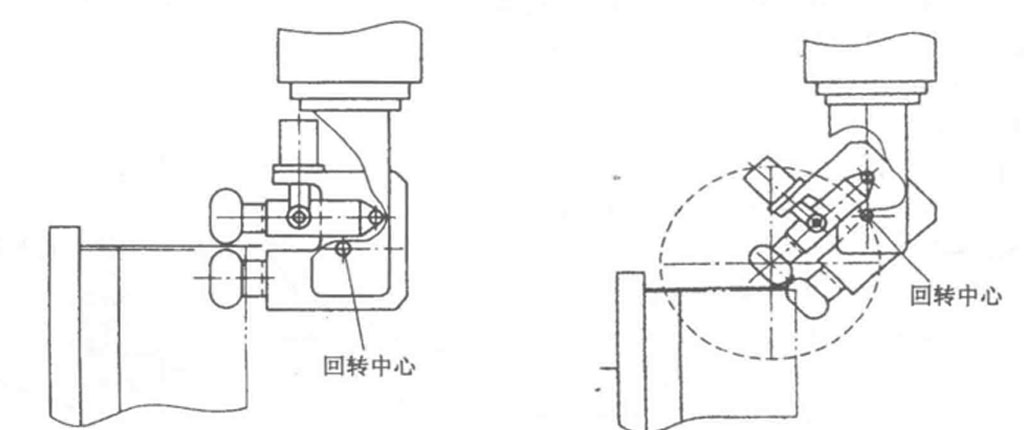
As depicted in Figure 2-42, this method utilizes two wheels to grip the straight edge of the workpiece, allowing it to rotate around a central axis to form a flange or bell mouth. This setup can be operated using CNC technology, offering great flexibility in shaping.
Flanging is further categorized into external and internal flanging, applicable to cylindrical, conical, and other shaped workpieces. It frequently serves as a preparatory step for subsequent operations such as curling and trimming.
Curling Forming
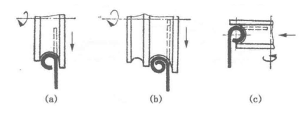
Many workpieces require curling to blunt their edges and enhance structural rigidity, as shown in Figure 2-43. Depending on the specific requirements, curling can be classified into mild curling (Figure a) and heavy curling (Figure b). Moreover, the orientation of the flange dictates whether the curling is vertical (Figures a and b) or lateral (Figure c). Empirical data indicates that the extent of radial (lateral) curling correlates with the wall thickness of the workpiece, as summarized in Table 2-6. Designing appropriately shaped curling wheels and mitigating the formation of wrinkles during the curling process are critical factors for successful execution.
| Workpiece wall thickness (mm) | Radial hemming dimension (mm) | Workpiece wall thickness (mm) | Radial hemming size range (mm) |
| 0.3 | 1.5~2.5 | 2.0 | 8~18 |
| 0.5 | 2.5~3.5 | 2.5 | 14~~22 |
| 1.0 | 4~~8 | 3.0 | 18~24 |
| 1.5 | 5~14 | 4.0 | 20~30 |
(1) Design of Curling Wheel Profiles
The basic profile of a simple curling wheel consists of a single circular arc, as depicted in Figure 2-44. Here, r represents the radius of the curling arc, which correlates with the outer radius of the curling circle and depends on the wall thickness and material properties of the workpiece. The diameters d1 and d2 of the cylindrical segments at both ends of the curling wheel are such that d1 < d2. The end face of d1 incorporates a flat surface, functioning as the guide for the workpiece’s flange and facilitating the flow of metal material. Curling wheel designs vary, with some consisting of multiple arcs (typically 2 to 3) or specialized curves, such as Archimedean spirals.
(2) Control of Curling Wrinkles
Curling can be performed on universal spinning machines, dedicated equipment, or even conventional lathes. During the curling process, there exists a possibility of wrinkle formation, primarily attributed to factors such as insufficient wall thickness, excessive feed rates, non-uniform wall thickness prior to curling, and misalignment during clamping. Thus, preemptive measures should be taken to address and correct these issues prior to curling.
Lap Joining Forming
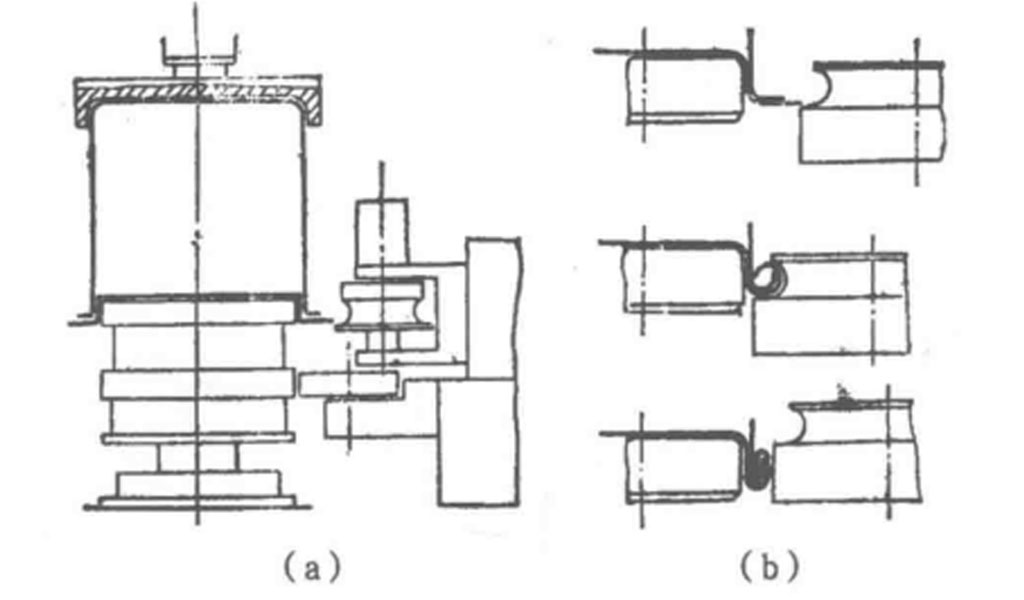
To facilitate the simultaneous curling and precise overlap of the edges of two hollow rotating body workpieces, the lap joining method illustrated in Figure 2-45 may be employed. Figure a depicts a single-wheel lap joining scenario, while Figure b shows the process of joining the workpieces. The structure of the lap joining wheel mirrors that of the flanging wheel shown in Figure 2-39, comprising an arcuate section and a cylindrical section. As the two workpieces are stacked and rotated, the arcuate section first curls their edges together, followed by the cylindrical section flattening the curl. A sealing adhesive may be applied in between to ensure airtightness.
To enhance forming efficiency, a specialized dual-wheel forming apparatus may be utilized (Figure 5-127). The dual-wheel forming die, as depicted in Figure 2-46, showcases the process. The first wheel completes the progressive curling, while the second wheel compresses the layered edges to form a tight seal. This lap joining technique is closely related to curling and finds extensive applications in the processing of containers for powders and liquids, including iron barrels, boxes, cans, and vessels made of aluminum and stainless steel.
Grooving and Rib Rolling Forming
To meet packaging, welding, or rigidity enhancement requirements, workpieces often undergo grooving and rib rolling, as illustrated in Figures 2-47 and 2-48. These processes utilize eccentric core molds or eccentric internal rollers.
Trimming and Bottom Cutting Operations
Before and after conventional spinning, workpieces frequently require trimming or bottom cutting of their flanges. Common trimming methods for the flanges of workpieces are depicted in Figure 2-49. Figure a illustrates the use of a rolling cutter in conjunction with a core mold shoulder for trimming, while Figure b shows the application of a cutting roller with a fixed guide on a standard core mold surface. When designing such cutting rollers, it is crucial to ensure that the cutter does not make contact with the core mold. This is achieved by incorporating a cylindrical step on the cutting roller, creating a gap that allows the cutter edge to remain clear of the core mold’s surface. As a result, the residual thickness of the workpiece at the cut edge can be precisely controlled to facilitate fracture. Figures c and d illustrate the use of dual cutting rollers for trimming, albeit at different orientations. During operation, the cutting edges of both rollers engage the workpiece wall on opposing sides, and the handles, coupled with an eccentric mechanism, enable the cutter edges to move towards each other for effective trimming. The aforementioned trimming methods have limited cutting thickness, typically ranging from 1 to 3 millimeters. For thicker workpieces, the cutting methods depicted in Figures e and f—utilizing turning tools—are recommended. Figure c showcases flat or angled blades for trimming the flange, while Figure f depicts a pointed blade cutting the workpiece’s side. Figure 5-62 features an angled scraping tool designed for concurrent spinning and scraping of the edge of the workpiece, ensuring that cutting is completed as the spinning operation concludes, with the scraping tool’s holder being adjustable and lockable.
Maximize Tooling and CNC Metal Spinning Capabilities.

At BE-CU China Metal Spinning company, we make the most of our equipment while monitoring signs of excess wear and stress. In addition, we look into newer, modern equipment and invest in those that can support or increase our manufacturing capabilities. Our team is very mindful of our machines and tools, so we also routinely maintain them to ensure they don’t negatively impact your part’s quality and productivity.
Talk to us today about making a rapid prototype with our CNC metal spinning service. Get a direct quote by chatting with us here or request a free project review.
BE-CU China CNC Metal Spinning service include : CNC Metal Spinning,Metal Spinning Die,Laser Cutting, Tank Heads Spinning,Metal Hemispheres Spinning,Metal Cones Spinning,Metal Dish-Shaped Spinning,Metal Trumpet Spinning,Metal Venturi Spinning,Aluminum Spinning Products,Stainless Steel Spinning Products,Copper Spinning Products,Brass Spinning Products,Steel Spinning Product,Metal Spinnin LED Reflector,Metal Spinning Pressure Vessel,
