Computer Numerical Control (CNC) spinning is an advanced manufacturing process that leverages automated machinery to form metal into complex shapes through rotational deformation. Among its many applications, the spinning of large center distance arc cams represents a specialized subset of this technology, blending precision engineering with sophisticated control systems. This article explores the principles, processes, machinery, and scientific underpinnings of CNC spinning as applied to large center distance arc cams, offering a detailed examination of its mechanics, applications, and comparative advantages.
Historical Context and Evolution of CNC Spinning
The origins of metal spinning trace back to ancient craftsmanship, where artisans manually shaped metal over rotating molds using rudimentary tools. This labor-intensive process evolved significantly with the Industrial Revolution, which introduced mechanized lathes. The advent of numerical control in the mid-20th century, pioneered by John T. Parsons and the Massachusetts Institute of Technology, marked a transformative leap. By the 1950s, early CNC systems began to emerge, integrating punched tape instructions with servo motors to automate tool movements.
CNC spinning, as a derivative of these developments, gained traction in the late 20th century as industries demanded higher precision and repeatability. The application to arc cams—mechanical components with curved profiles used in motion control—emerged as a response to the need for complex geometries in automotive, aerospace, and industrial machinery. Large center distance arc cams, characterized by significant spacing between rotational axes, posed unique challenges that spurred further innovation in CNC spinning technology, culminating in the sophisticated systems available as of March 23, 2025.
Principles of CNC Spinning
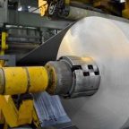
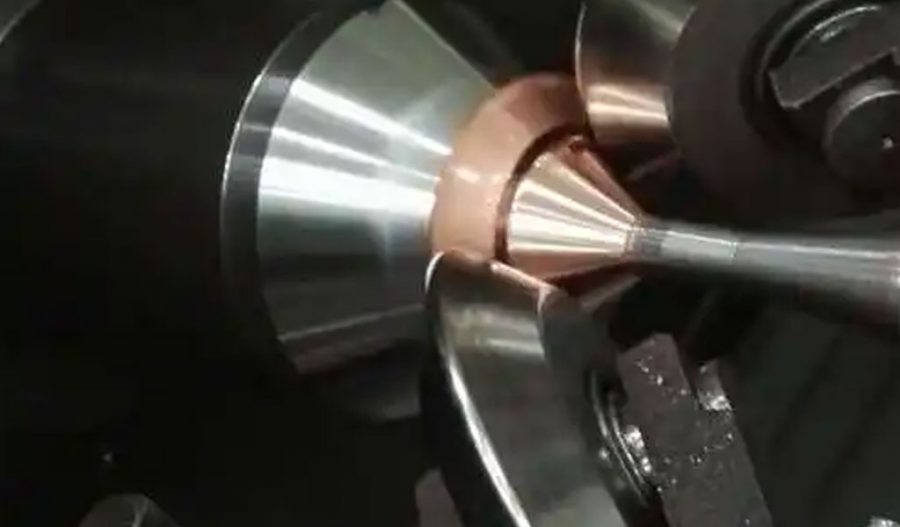
CNC spinning involves the deformation of a metal blank—typically a flat sheet or pre-formed tube—over a mandrel or die that rotates at high speed. A spinning tool, controlled by a CNC system, applies localized pressure to shape the material incrementally. Unlike traditional machining processes that remove material, spinning is a chipless forming technique, relying on plastic deformation to achieve the desired geometry.
For large center distance arc cams, the process must accommodate the extended spatial relationship between the cam’s rotational center and its outer profile. This necessitates precise coordination of multiple axes, typically including the spindle rotation (C-axis), linear feed axes (X and Z), and sometimes additional rotary axes (A or B). The CNC controller interprets G-code instructions—standardized commands such as G02 (clockwise arc) and G03 (counterclockwise arc)—to orchestrate these movements, ensuring the tool follows the cam’s curvature with sub-millimeter accuracy.
The material’s ductility is critical in spinning. Common materials include aluminum, steel, and titanium alloys, selected based on their formability and strength. The process induces work hardening, enhancing the component’s mechanical properties, but also requires careful control to prevent cracking or excessive thinning.
Mechanics of Large Center Distance Arc Cams
An arc cam is a mechanical device that translates rotational motion into linear or oscillatory motion via a curved profile. The “large center distance” designation refers to the substantial separation between the cam’s rotational axis and the follower’s contact point, often exceeding 200 mm in industrial applications. This configuration is prevalent in machinery requiring extended reach or amplified motion, such as indexing mechanisms or heavy-duty actuators.
The geometry of a large center distance arc cam typically features a globoidal or cylindrical profile with a pronounced arcuate path. Unlike planar cams, which operate in two dimensions, arc cams often exhibit three-dimensional curvature, complicating their manufacture. The center distance influences the cam’s kinematics, affecting the follower’s displacement, velocity, and acceleration. Mathematically, the cam profile can be expressed as a function of angular position (θ):
r(θ)=r0+f(θ)
where r0 r_0 r0 is the base radius, and f(θ) f(\theta) f(θ) defines the arcuate deviation, often modeled using splines or trigonometric functions for smooth transitions.
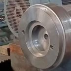
In CNC spinning, achieving this profile requires a mandrel that mirrors the cam’s final shape. The spinning tool traces the mandrel’s surface, deforming the blank to conform to its contours. For large center distances, the mandrel’s size and the tool’s reach become limiting factors, necessitating specialized equipment.
CNC Spinning Machinery for Large Center Distance Arc Cams
Modern CNC spinning machines designed for large center distance arc cams are engineering marvels, integrating robust mechanical structures with advanced control systems. A typical machine features a horizontal or vertical spindle, capable of speeds up to 3,000 RPM, and a multi-axis tool turret. The key components include:
- Spindle and Chuck: The spindle rotates the mandrel and blank, while the chuck secures them against vibrational forces. For large center distance cams, chucks must accommodate oversized mandrels, often exceeding 500 mm in diameter.
- Tooling System: Spinning rollers, typically made of hardened steel or carbide, apply pressure to the blank. Adjustable tool holders allow for variable center distances, ranging from 40 to 350 mm in some models.
- CNC Controller: A microprocessor interprets G-code, coordinating axes with precision down to 0.001 mm. Modern controllers, such as those from Siemens or Fanuc, support real-time feedback via encoders.
- Linear and Rotary Axes: Machines often employ five or more axes (X, Y, Z, A, B) to navigate the complex geometry of arc cams. The B-axis, for instance, tilts the tool to maintain contact with the cam’s curvature.
A notable example is the five-axis CNC spinning lathe, which combines linear motion (X, Y, Z) with rotational adjustments (A, B). Such machines can adjust the center distance dynamically, adapting to cams with distances up to 280 mm or more, as demonstrated in studies from Northwestern Polytechnical University.
Process Parameters and Optimization
The success of CNC spinning for large center distance arc cams hinges on optimizing process parameters. Key variables include:
- Spindle Speed: Typically ranges from 500 to 2,000 RPM, depending on material and cam size. Higher speeds reduce forming time but increase heat generation.
- Feed Rate: The rate at which the tool advances along the blank, measured in mm/min. Values between 100 and 500 mm/min balance efficiency and surface quality.
- Tool Pressure: Excessive pressure risks material failure, while insufficient pressure prolongs the process. Optimal pressure varies with material thickness, often 1–5 mm for steel blanks.
- Center Distance Adjustment: For large center distance cams, the machine must maintain a constant separation between rotational axes, adjustable via a W-axis mechanism in some designs.
Optimization often employs simulation software, such as MasterCAM or SolidWorks, to predict deformation patterns and stress distribution. Finite Element Analysis (FEA) models the blank’s response to spinning forces, ensuring the final cam meets dimensional tolerances (e.g., ±0.01 mm).
Comparative Analysis of CNC Spinning vs. Alternative Methods
CNC spinning competes with other manufacturing techniques, such as milling, forging, and casting, for producing large center distance arc cams. Each method offers distinct advantages and limitations, as detailed in the table below:
| Method | Precision (mm) | Production Speed | Material Waste | Complexity Limit | Cost per Unit |
|---|---|---|---|---|---|
| CNC Spinning | ±0.01 | Moderate (10–20 min) | Low | High | Medium ($50–100) |
| CNC Milling | ±0.005 | Slow (30–60 min) | High | Very High | High ($100–200) |
| Forging | ±0.1 | Fast (1–5 min) | Moderate | Moderate | Low ($20–50) |
| Casting | ±0.5 | Fast (2–10 min) | Low | Low | Low ($10–30) |
- CNC Spinning: Excels in producing seamless, high-strength cams with minimal waste. Its chipless nature reduces material costs, though setup times are longer than forging or casting.
- CNC Milling: Offers superior precision but generates significant waste and requires multiple setups for complex geometries, increasing time and cost.
- Forging: Ideal for high-volume production of simpler cams, but lacks the flexibility to handle intricate arc profiles without secondary machining.
- Casting: Cost-effective for mass production, but poor precision and surface finish necessitate additional processing for critical applications.
For large center distance arc cams, CNC spinning strikes a balance between precision and efficiency, particularly when cam profiles demand smooth, continuous surfaces.
Material Considerations and Mechanical Properties
Material selection profoundly impacts the spinning process and the cam’s performance. Common choices include:
- Aluminum Alloys (e.g., 6061-T6): Lightweight and highly formable, with a yield strength of 276 MPa. Ideal for aerospace applications but prone to galling during spinning.
- Carbon Steel (e.g., AISI 1045): Offers a yield strength of 530 MPa and good ductility. Requires higher tool pressure and careful heat management.
- Titanium Alloys (e.g., Ti-6Al-4V): Exceptional strength-to-weight ratio (900 MPa yield) but challenging to spin due to low ductility and high springback.
Spinning induces strain hardening, increasing hardness and tensile strength by 10–20% compared to the raw material. However, this can reduce ductility, necessitating annealing in some cases. The table below compares material properties pre- and post-spinning:
| Material | Yield Strength (MPa) | Tensile Strength (MPa) | Elongation (%) | Hardness (HB) |
|---|---|---|---|---|
| 6061-T6 (Pre) | 276 | 310 | 12 | 95 |
| 6061-T6 (Post) | 310 | 340 | 8 | 105 |
| AISI 1045 (Pre) | 530 | 625 | 16 | 180 |
| AISI 1045 (Post) | 600 | 700 | 10 | 200 |
| Ti-6Al-4V (Pre) | 900 | 950 | 10 | 330 |
| Ti-6Al-4V (Post) | 980 | 1020 | 6 | 350 |
Applications in Industry
Large center distance arc cams produced via CNC spinning find applications across multiple sectors:
- Automotive: Used in camshafts and transmission systems, where precise motion control enhances engine efficiency.
- Aerospace: Employed in actuator mechanisms for flaps and landing gear, leveraging lightweight materials like aluminum and titanium.
- Industrial Machinery: Integral to indexing tables and robotic arms, where large center distances enable extended reach and smooth operation.
As of March 23, 2025, advancements in CNC spinning have expanded its use in emerging fields like renewable energy, where cams control turbine blade adjustments.
Challenges and Limitations
Despite its advantages, CNC spinning of large center distance arc cams faces several challenges:
- Tool Wear: High contact pressures accelerate roller degradation, requiring frequent replacement or reconditioning.
- Material Thinning: Localized deformation can reduce wall thickness by up to 30%, compromising structural integrity if not monitored.
- Machine Rigidity: Large center distances demand extended spindle overhangs, reducing stiffness and potentially affecting precision.
Mitigation strategies include adaptive control systems, which adjust tool paths in real time based on sensor feedback, and hybrid processes combining spinning with milling for critical features.
Future Directions and Innovations
The future of CNC spinning for large center distance arc cams lies in automation and material science. Developments as of 2025 include:
- AI Integration: Machine learning algorithms optimize spinning parameters, reducing trial-and-error in setup.
- Advanced Materials: Composites and high-entropy alloys promise enhanced performance, though their formability remains under study.
- Hybrid Manufacturing: Combining spinning with additive manufacturing allows for complex mandrels and bespoke cam designs.
Research institutions, such as xAI and Northwestern Polytechnical University, continue to push the boundaries, with recent studies exploring six-axis spinning systems for even greater geometric flexibility.
Conclusion
CNC spinning of large center distance arc cams represents a pinnacle of modern manufacturing, merging traditional metal forming with cutting-edge automation. Its ability to produce precise, durable components with minimal waste positions it as a vital technology in engineering. As machinery and materials evolve, this process will likely expand its reach, addressing the demands of increasingly sophisticated industrial applications.
Maximize Tooling and CNC Metal Spinning Capabilities.
At BE-CU China Metal Spinning company, we make the most of our equipment while monitoring signs of excess wear and stress. In addition, we look into newer, modern equipment and invest in those that can support or increase our manufacturing capabilities. Our team is very mindful of our machines and tools, so we also routinely maintain them to ensure they don’t negatively impact your part’s quality and productivity.
Talk to us today about making a rapid prototype with our CNC metal spinning service. Get a direct quote by chatting with us here or request a free project review.
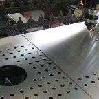
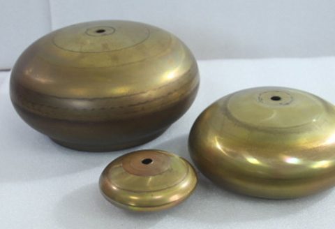
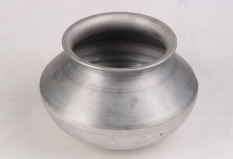
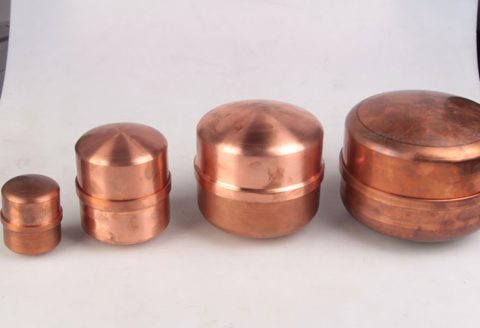
BE-CU China CNC Metal Spinning service include : CNC Metal Spinning,Metal Spinning Die,Laser Cutting, Tank Heads Spinning,Metal Hemispheres Spinning,Metal Cones Spinning,Metal Dish-Shaped Spinning,Metal Trumpet Spinning,Metal Venturi Spinning,Aluminum Spinning Products,Stainless Steel Spinning Products,Copper Spinning Products,Brass Spinning Products,Steel Spinning Product,Metal Spinnin LED Reflector,Metal Spinning Pressure Vessel,