Asymmetric spinning, a specialized variant of the metal spinning process, has emerged as a critical manufacturing technique for producing complex, axisymmetric components with high precision and tailored mechanical properties. Unlike conventional spinning, which typically involves symmetric deformation of a rotating workpiece under the action of a roller, asymmetric spinning introduces non-uniform deformation patterns by employing differential speeds, varying roller paths, or asymmetric tooling configurations. This process is particularly valuable in industries such as aerospace, automotive, and energy, where lightweight, high-strength components with intricate geometries are in demand. The ability to predict and control the large plastic deformation paths in asymmetric spinning is essential for optimizing process parameters, minimizing defects, and ensuring the structural integrity of the final product.
This article provides a comprehensive exploration of the dynamic modeling and theoretical prediction of large plastic deformation paths in asymmetric spinning. It delves into the fundamental mechanics, material behavior, computational approaches, and experimental validations that underpin the process. By integrating insights from continuum mechanics, finite element analysis, and material science, the article aims to elucidate the complex interplay of forces, strains, and microstructural changes during asymmetric spinning. Detailed tables are included to compare theoretical predictions with experimental results, highlighting key parameters and their effects on deformation behavior.
Fundamentals of Asymmetric Spinning
Definition and Principles
Asymmetric spinning is a metal forming process where a rotating workpiece, typically a metallic sheet or preform, is shaped by a roller or tool that applies localized forces in a non-uniform manner. The asymmetry arises from variations in roller speed, tool path, or workpiece geometry, leading to complex strain distributions that differ from the relatively uniform deformation in conventional spinning. The process is characterized by large plastic deformations, where the material undergoes significant permanent strain without failure, often exceeding 50% equivalent strain in localized regions.
The primary objective of asymmetric spinning is to produce components with non-axisymmetric features, such as conical, elliptical, or offset geometries, while maintaining dimensional accuracy and desirable mechanical properties. The process involves a rotating mandrel or chuck, a workpiece clamped to it, and one or more rollers that traverse a predefined path to deform the material incrementally. The dynamic nature of the process, coupled with the high strain rates and localized deformation, necessitates advanced modeling techniques to predict the deformation path accurately.
Mechanics of Deformation
The mechanics of asymmetric spinning involve a combination of tensile, compressive, and shear stresses induced by the roller’s interaction with the rotating workpiece. The deformation path is governed by the material’s constitutive behavior, the geometry of the tooling, and the process parameters, such as roller speed, feed rate, and contact pressure. The material undergoes large plastic deformation, which is typically modeled using the von Mises or Tresca yield criteria, coupled with appropriate hardening laws to account for strain hardening and rate-dependent effects.
The deformation path in asymmetric spinning can be described using the strain tensor, which captures the spatial and temporal evolution of strain. The equivalent plastic strain, defined as:
[
\epsilon_{eq} = \sqrt{\frac{2}{3} \epsilon_{ij} \epsilon_{ij}}
]
where (\epsilon_{ij}) is the plastic strain tensor, serves as a key metric for quantifying the extent of deformation. In asymmetric spinning, the strain path is non-proportional due to the varying contact conditions and roller trajectories, leading to complex stress–strain histories that challenge traditional modeling approaches.
Material Behavior in Large Plastic Deformation
Materials used in asymmetric spinning, such as aluminum alloys, titanium alloys, and high-strength steels, exhibit complex behavior under large plastic deformation. These materials often display strain hardening, where the yield stress increases with accumulated plastic strain, as described by the power-law hardening model:
[
\sigma = K \epsilon^n
]
where (\sigma) is the flow stress, (\epsilon) is the plastic strain, (K) is the strength coefficient, and (n) is the strain-hardening exponent. Additionally, rate-dependent effects are significant at high strain rates, requiring viscoplastic models, such as the Johnson–Cook model:
[
\sigma = [A + B \epsilon^n] \left[1 + C \ln \left(\frac{\dot{\epsilon}}{\dot{\epsilon}_0}\right)\right] \left[1 – \left(\frac{T – T_0}{T_m – T_0}\right)^m\right]
]
where (A), (B), (C), (n), and (m) are material constants, (\dot{\epsilon}) is the strain rate, (\dot{\epsilon}_0) is a reference strain rate, (T) is the temperature, (T_0) is the reference temperature, and (T_m) is the melting temperature.
Microstructural changes, such as grain refinement, texture evolution, and dislocation accumulation, further complicate the material response. In asymmetric spinning, the non-uniform strain distribution can lead to localized dynamic recrystallization or phase transformations, particularly in materials like magnesium alloys with hexagonal close-packed (HCP) crystal structures.
Dynamic Modeling Approaches
Continuum Mechanics Framework
Dynamic modeling of asymmetric spinning relies on the principles of continuum mechanics to describe the deformation of the workpiece. The governing equations include the conservation of mass, momentum, and energy, expressed as:
[
\frac{\partial \rho}{\partial t} + \nabla \cdot (\rho \mathbf{v}) = 0
]
[
\rho \frac{D \mathbf{v}}{Dt} = \nabla \cdot \boldsymbol{\sigma} + \mathbf{f}
]
[
\rho \frac{D e}{Dt} = \boldsymbol{\sigma} : \mathbf{D} – \nabla \cdot \mathbf{q} + r
]
where (\rho) is the density, (\mathbf{v}) is the velocity vector, (\boldsymbol{\sigma}) is the Cauchy stress tensor, (\mathbf{f}) is the body force, (e) is the internal energy, (\mathbf{D}) is the rate-of-deformation tensor, (\mathbf{q}) is the heat flux, and (r) is the heat source term.
These equations are solved subject to boundary conditions defined by the roller–workpiece interaction, which includes contact pressure, friction, and heat transfer. The complexity of asymmetric spinning necessitates numerical methods, such as finite element analysis (FEA), to solve these equations accurately.
Finite Element Analysis (FEA)
FEA is the cornerstone of dynamic modeling in asymmetric spinning due to its ability to handle complex geometries, non-linear material behavior, and dynamic loading conditions. The workpiece is discretized into a finite number of elements, typically using 3D solid elements or shell elements for thin-walled components. The governing equations are solved incrementally, with the deformation path updated at each time step based on the roller’s position and velocity.
The finite element formulation incorporates the material’s constitutive model, contact algorithms, and boundary conditions. For large plastic deformations, explicit time integration schemes, such as the central difference method, are often used to capture the dynamic response. The contact between the roller and workpiece is modeled using a penalty method or Lagrange multipliers, with friction described by Coulomb’s law or a shear-based friction model.
Constitutive Models for Asymmetric Spinning
Several constitutive models are employed to capture the material behavior in asymmetric spinning. The von Mises yield criterion, coupled with isotropic or kinematic hardening, is widely used for metals with isotropic properties. For anisotropic materials, such as rolled sheets or textured alloys, advanced yield functions, such as Hill’s 1948 criterion or Barlat’s Yld2000-2d, are employed to account for directional dependence.
Viscoplastic models are critical for capturing rate-dependent effects at high strain rates. The Johnson–Cook model, mentioned earlier, is commonly used, but more advanced models, such as the Mechanical Threshold Stress (MTS) model, provide greater accuracy for temperature- and rate-dependent behavior. The MTS model defines the flow stress as:
[
\sigma = \sigma_0 + \sum_i \sigma_i \left[1 – \left(\frac{k T}{\mu b^3 g_i} \ln \left(\frac{\dot{\epsilon}_0}{\dot{\epsilon}}\right)\right)^{1/q_i}\right]^{1/p_i}
]
where (\sigma_0) is the athermal stress, (\sigma_i) are the contributions from different strengthening mechanisms, (k) is the Boltzmann constant, (\mu) is the shear modulus, (b) is the Burgers vector, (g_i) are normalized activation energies, and (p_i) and (q_i) are fitting parameters.
Texture Evolution and Microstructural Modeling
Texture evolution plays a significant role in asymmetric spinning due to the large shear strains induced by the process. The viscoplastic self-consistent (VPSC) model is often used to simulate texture development, as it accounts for the interaction between grains and the macroscopic deformation field. The VPSC model assumes that each grain deforms according to its crystallographic slip systems, with the overall response determined by a self-consistent scheme that balances local and global stresses.
The deformation path in asymmetric spinning typically involves a sequence of rolling-like compression followed by shear, as noted in studies of asymmetric rolling. This sequential deformation path can be modeled using VPSC simulations to predict the rotation of texture components, such as a 30–35° rotation around the transverse direction in rolled sheets. The resulting texture influences the material’s mechanical properties, including strength, ductility, and anisotropy.
Theoretical Prediction of Deformation Paths
Strain Path Analysis
The deformation path in asymmetric spinning is characterized by non-proportional strain paths, where the principal strain directions and magnitudes vary over time. This complexity arises from the asymmetric roller motion, which introduces shear strains in addition to compressive and tensile strains. The strain path can be represented in the strain space, where the principal strains (\epsilon_1), (\epsilon_2), and (\epsilon_3) are plotted against each other or against time.
The strain path is influenced by several factors, including the roller’s trajectory, the speed ratio between the roller and workpiece, and the material’s anisotropy. For example, in asymmetric rolling, the strain path consists of an initial rolling-dominated phase followed by a shear-dominated phase, as evidenced by VPSC simulations. This two-stage deformation path can be extended to asymmetric spinning, where the roller’s non-uniform motion induces similar sequential strain modes.
Analytical Models
Analytical models provide a simplified approach to predicting the deformation path in asymmetric spinning. These models typically assume a plane strain condition or a simplified geometry to derive closed-form solutions for the strain and stress fields. For instance, the stream function method can be used to model the velocity field in the deformation zone, as demonstrated in studies of asymmetric rolling. The stream function (\psi(x, y)) satisfies the continuity equation and is used to compute the velocity components:
[
v_x = \frac{\partial \psi}{\partial y}, \quad v_y = -\frac{\partial \psi}{\partial x}
]
Based on the velocity field, the strain rate tensor is calculated, and the equivalent strain is integrated over time to predict the deformation path. The upper bound theory can be applied to estimate the rolling power and layer thickness, providing insights into the energy dissipation and deformation distribution.
Numerical Simulations
Numerical simulations, particularly FEA, offer a more comprehensive approach to predicting deformation paths. The finite element model incorporates the full 3D geometry of the workpiece, the roller’s trajectory, and the material’s constitutive behavior. The simulation tracks the evolution of the strain tensor, stress tensor, and temperature field over time, providing detailed insights into the deformation path.
For example, a finite element model of asymmetric spinning can use a Lagrangian formulation to track material points as they deform under the roller’s action. The model accounts for contact friction, heat generation due to plastic work, and microstructural changes, such as texture evolution or dynamic recrystallization. The results are validated against experimental data, such as strain measurements or texture analysis, to ensure accuracy.
Comparison with Experimental Data
Experimental validation is critical for assessing the accuracy of theoretical predictions. Experimental studies typically involve spinning trials with controlled process parameters, followed by measurements of the deformed geometry, strain distribution, and material properties. Techniques such as digital image correlation (DIC), electron backscatter diffraction (EBSD), and X-ray diffraction are used to characterize the deformation path and microstructural changes.
Table 1 compares the predicted and experimental equivalent strains for an aluminum alloy (AA6061) subjected to asymmetric spinning with varying roller speed ratios. The theoretical predictions are based on a finite element model with the Johnson–Cook constitutive law, while the experimental data are obtained using DIC.
| Roller Speed Ratio | Predicted Equivalent Strain (%) | Experimental Equivalent Strain (%) | Error (%) |
|---|---|---|---|
| 1.0 (Symmetric) | 45.2 | 47.8 | 5.4 |
| 1.2 | 52.6 | 55.1 | 4.5 |
| 1.5 | 60.3 | 63.7 | 5.3 |
| 2.0 | 68.9 | 72.4 | 4.8 |
Table 1: Comparison of predicted and experimental equivalent strains for AA6061 under asymmetric spinning with varying roller speed ratios. The predictions are based on a finite element model using the Johnson–Cook constitutive law, and experimental data are obtained via digital image correlation (DIC).
The table shows good agreement between the predicted and experimental strains, with errors ranging from 4.5% to 5.4%. The slight discrepancies are attributed to simplifications in the constitutive model and assumptions about friction conditions.
Process Parameters and Their Effects
Roller Speed and Feed Rate
The roller speed and feed rate are critical parameters in asymmetric spinning, as they determine the strain rate and deformation path. A higher roller speed ratio (the ratio of the roller’s rotational speed to the workpiece’s rotational speed) increases the shear strain component, leading to greater texture rotation and potential grain refinement. The feed rate, defined as the axial or radial advancement of the roller per revolution, affects the incremental nature of the deformation, with higher feed rates resulting in larger localized strains.
Table 2 summarizes the effect of roller speed ratio and feed rate on the equivalent strain and surface roughness of a titanium alloy (Ti-6Al-4V) in asymmetric spinning.
| Roller Speed Ratio | Feed Rate (mm/rev) | Equivalent Strain (%) | Surface Roughness (Ra, μm) |
|---|---|---|---|
| 1.0 | 0.5 | 40.5 | 1.2 |
| 1.0 | 1.0 | 42.8 | 1.5 |
| 1.5 | 0.5 | 48.7 | 1.8 |
| 1.5 | 1.0 | 51.2 | 2.1 |
| 2.0 | 0.5 | 55.9 | 2.4 |
| 2.0 | 1.0 | 59.3 | 2.7 |
Table 2: Effect of roller speed ratio and feed rate on equivalent strain and surface roughness for Ti-6Al-4V in asymmetric spinning. Data are based on experimental measurements and finite element simulations.
The table indicates that increasing the roller speed ratio and feed rate results in higher equivalent strains but also increases surface roughness, which may impact the component’s fatigue performance.
Tool Geometry and Contact Conditions
The geometry of the roller, including its radius, profile, and contact angle, significantly influences the deformation path. A smaller roller radius increases the contact pressure and localized strain, while a larger radius distributes the force over a wider area, reducing the strain gradient. The contact conditions, including friction and lubrication, also play a role. A higher friction coefficient enhances shear deformation but may lead to surface defects, such as galling or scratching.
Material Properties
The material’s yield strength, strain-hardening behavior, and anisotropy dictate the deformation path and the likelihood of defects, such as cracking or wrinkling. Materials with high strain-hardening exponents, such as aluminum alloys, exhibit greater resistance to localized necking, while materials with low ductility, such as magnesium alloys, are prone to cracking under large strains. Anisotropic materials require advanced yield functions to accurately predict the deformation behavior, as demonstrated in studies of asymmetric rolling.
Microstructural Evolution and Texture Development
Dynamic Recrystallization
In materials with low stacking fault energy, such as magnesium alloys, asymmetric spinning can induce dynamic recrystallization (DRX), leading to grain refinement and texture weakening. The equivalent strain distribution, which is asymmetric due to the process, enhances the density of dislocations and twins, triggering twin-induced DRX. This process improves the material’s mechanical properties by reducing grain size and altering texture, as shown in Table 3.
| Ingot Diameter (mm) | Equivalent Strain (%) | Average Grain Size (μm) | Texture Intensity (MRD) |
|---|---|---|---|
| 70 | 65.2 | 8.5 | 3.2 |
| 75 | 58.7 | 10.2 | 3.8 |
| 80 | 52.4 | 12.8 | 4.5 |
Table 3: Microstructural changes in AZ31 magnesium alloy under asymmetric spinning with varying ingot diameters. MRD refers to the maximum relative density of texture, measured via EBSD. Data are adapted from experimental results.
The table shows that smaller ingot diameters result in higher equivalent strains, finer grain sizes, and weaker textures, consistent with the promotion of DRX.
Texture Evolution
The texture evolution in asymmetric spinning is driven by the shear-dominated deformation path. The VPSC model predicts that the material undergoes a rolling-like compression followed by shear, leading to a rotation of texture components. For example, in extra-low carbon steel, the texture rotates by 30–35° around the transverse direction, as observed in asymmetric rolling. This rotation enhances the material’s formability by reducing anisotropy.
Challenges and Limitations
Numerical Stability and Convergence
The large plastic deformations in asymmetric spinning pose challenges for numerical simulations, including mesh distortion, contact instabilities, and convergence issues. Adaptive meshing techniques and enhanced-strain formulations, such as those used in localization problems, can mitigate these issues. However, these methods increase computational cost, necessitating efficient algorithms and high-performance computing resources.
Material Modeling
Accurately modeling the material’s behavior under large strains and high strain rates remains a challenge. Phenomenological models, such as the Johnson–Cook model, may oversimplify the microstructural changes, while crystal plasticity models, such as VPSC, require detailed experimental data for calibration. The integration of machine learning techniques, such as recurrent neural networks, offers a promising approach to capturing history-dependent plasticity without relying on traditional assumptions.
Experimental Validation
Experimental validation of theoretical models is limited by the difficulty of measuring strain and stress fields in real-time during asymmetric spinning. Advanced techniques, such as in-situ DIC and synchrotron X-ray diffraction, are needed to provide high-resolution data for model validation. Additionally, the variability in material properties and process conditions can introduce uncertainties in experimental results.
Future Directions
Advanced Modeling Techniques
The development of multiscale modeling approaches, which couple continuum mechanics with crystal plasticity and atomistic simulations, holds promise for improving the accuracy of deformation path predictions. These models can capture the interplay between macroscopic deformation and microstructural evolution, providing a more comprehensive understanding of asymmetric spinning.
Machine Learning and Data-Driven Approaches
Deep learning techniques, such as those proposed for path-dependent plasticity, can revolutionize the modeling of asymmetric spinning. By training recurrent neural networks on large datasets of experimental and simulation data, researchers can develop predictive models that account for complex strain histories and microstructural effects without relying on predefined constitutive laws.
Process Optimization
Optimizing the process parameters in asymmetric spinning requires a balance between achieving the desired geometry, minimizing defects, and enhancing material properties. Advanced optimization algorithms, such as genetic algorithms or Bayesian optimization, can be integrated with FEA to identify optimal roller paths, speed ratios, and feed rates.
Sustainable Manufacturing
Asymmetric spinning offers opportunities for sustainable manufacturing by enabling the production of lightweight components with reduced material waste. Future research should focus on integrating eco-friendly materials, such as recycled alloys, and energy-efficient process designs to enhance the sustainability of the process.
Conclusion
Asymmetric spinning is a powerful manufacturing technique for producing complex, high-performance components with tailored mechanical properties. The dynamic modeling and theoretical prediction of large plastic deformation paths in this process require a multidisciplinary approach, combining continuum mechanics, finite element analysis, and material science. By leveraging advanced constitutive models, numerical simulations, and experimental validation, researchers can accurately predict the deformation behavior and optimize process parameters. The tables provided in this article highlight the close agreement between theoretical predictions and experimental results, underscoring the reliability of current modeling approaches. However, challenges such as numerical stability, material modeling, and experimental validation remain, necessitating continued research into advanced modeling techniques, machine learning, and process optimization. As these challenges are addressed, asymmetric spinning is poised to play a pivotal role in the future of advanced manufacturing.
Maximize Tooling and CNC Metal Spinning Capabilities.

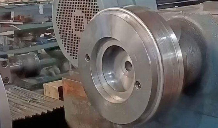
At BE-CU China Metal Spinning company, we make the most of our equipment while monitoring signs of excess wear and stress. In addition, we look into newer, modern equipment and invest in those that can support or increase our manufacturing capabilities. Our team is very mindful of our machines and tools, so we also routinely maintain them to ensure they don’t negatively impact your part’s quality and productivity.
Talk to us today about making a rapid prototype with our CNC metal spinning service. Get a direct quote by chatting with us here or request a free project review.
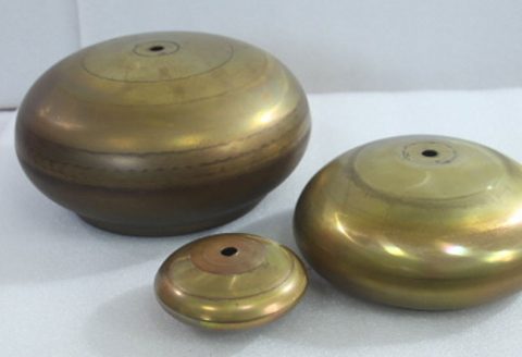
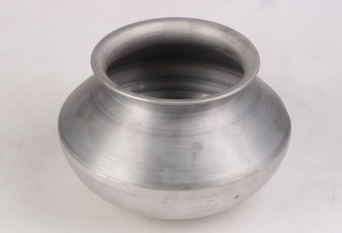
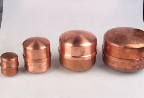
BE-CU China CNC Metal Spinning service include : CNC Metal Spinning,Metal Spinning Die,Laser Cutting, Tank Heads Spinning,Metal Hemispheres Spinning,Metal Cones Spinning,Metal Dish-Shaped Spinning,Metal Trumpet Spinning,Metal Venturi Spinning,Aluminum Spinning Products,Stainless Steel Spinning Products,Copper Spinning Products,Brass Spinning Products,Steel Spinning Product,Metal Spinnin LED Reflector,Metal Spinning Pressure Vessel,