Welding is a critical fabrication process used to join metals or thermoplastics by applying heat, pressure, or both, resulting in a strong, permanent bond. The quality of a weld directly impacts the structural integrity, safety, and longevity of the welded component. Identifying a good weld requires a systematic evaluation of multiple factors, including visual characteristics, mechanical properties, and compliance with industry standards. This article provides a comprehensive, scientifically structured checklist for assessing weld quality, encompassing visual inspection, non-destructive testing (NDT), destructive testing, and adherence to codes and standards. Designed for welders, inspectors, engineers, and quality control professionals, this guide includes detailed explanations, comparative tables, and references to authoritative standards such as those from the American Welding Society (AWS), International Organization for Standardization (ISO), and American Society for Testing and Materials (ASTM).
1. Introduction to Weld Quality Assessment
Weld quality assessment is a multidisciplinary process that combines visual inspection, testing methodologies, and adherence to standardized criteria to ensure that welds meet functional and safety requirements. A “good weld” is one that exhibits uniformity, strength, and durability while being free from defects such as cracks, porosity, or incomplete fusion. The importance of weld quality cannot be overstated, as welds are integral to industries such as construction, aerospace, automotive, shipbuilding, and energy production. Poor welds can lead to catastrophic failures, costly repairs, and safety hazards.
The checklist for identifying good welds is built on a foundation of objective criteria, including:
- Visual Inspection: Evaluating surface characteristics such as bead uniformity, penetration, and the absence of imperfections.
- Non-Destructive Testing (NDT): Using techniques like ultrasonic testing, radiographic testing, and magnetic particle inspection to detect internal defects without damaging the weld.
- Destructive Testing: Performing mechanical tests, such as tensile or bend tests, to assess the weld’s strength and ductility.
- Compliance with Standards: Ensuring welds meet specifications outlined by organizations like AWS, ISO, or ASME (American Society of Mechanical Engineers).
This article is structured to provide a step-by-step guide, with each section addressing a specific aspect of weld quality evaluation. Tables are included to compare weld characteristics, testing methods, and standards, facilitating a rigorous and scientific approach.
2. Fundamentals of Weld Imperfections and Quality Criteria
2.1 Understanding Weld Imperfections
Weld imperfections are deviations from the ideal weld that may compromise its performance. According to ISO 5817, weld imperfections are classified into six categories: cracks, cavities, solid inclusions, lack of fusion, imperfect shape, and miscellaneous imperfections. A good weld minimizes or eliminates these imperfections to ensure structural integrity.
- Cracks: Fractures in the weld or heat-affected zone (HAZ) caused by thermal stresses, hydrogen embrittlement, or improper cooling. Cracks are unacceptable in most standards due to their potential to propagate under load.
- Cavities: Gas entrapments, such as porosity or blowholes, resulting from improper shielding gas or contaminated materials. Small, isolated cavities may be acceptable within limits, but large or clustered cavities reduce weld strength.
- Solid Inclusions: Non-metallic particles, such as slag or flux, trapped within the weld. Inclusions can act as stress concentrators, weakening the weld.
- Lack of Fusion: Incomplete bonding between the weld metal and base material or between weld passes, often due to insufficient heat input or improper technique.
- Imperfect Shape: Deviations in weld geometry, such as excessive reinforcement, undercut, or irregular bead width, which can affect fatigue resistance and aesthetics.
- Miscellaneous Imperfections: Surface irregularities, such as spatter or arc strikes, that may not affect mechanical properties but can indicate poor welding practices.
2.2 Quality Levels and Acceptance Criteria
Weld quality is evaluated against acceptance criteria defined by standards such as ISO 5817, AWS D1.1, or ASME Section IX “¿Cómo se puede hacer un análisis de la calidad de una soldadura?”. These standards specify quality levels (e.g., ISO 5817 Levels B, C, D) based on the severity of imperfections and the application’s requirements. For example:
- Level B (Stringent): Suitable for critical applications like aerospace or pressure vessels, allowing minimal imperfections.
- Level C (Intermediate): Appropriate for structural steelwork, permitting moderate imperfections.
- Level D (Lenient): Used for non-critical applications, allowing more significant imperfections.
Table 1 compares the acceptance criteria for common imperfections across ISO 5817 quality levels.
Table 1: Comparison of Weld Imperfection Acceptance Criteria (ISO 5817)
| Imperfection Type | Level B (Stringent) | Level C (Intermediate) | Level D (Lenient) |
|---|---|---|---|
| Cracks | Not permitted | Not permitted | Not permitted |
| Porosity (max size) | 1 mm, max 0.2% of area | 2 mm, max 0.3% of area | 3 mm, max 0.5% of area |
| Lack of Fusion | Not permitted | Max 1 mm length, isolated | Max 2 mm length, isolated |
| Undercut (depth) | Max 0.5 mm, smooth transition | Max 1 mm, smooth transition | Max 1.5 mm, smooth transition |
| Excess Penetration | Max 2 mm | Max 3 mm | Max 4 mm |
2.3 Weld Imperfection Causes and Remedies
Understanding the causes of imperfections is essential for producing high-quality welds. Common causes include:
- Improper Technique: Incorrect electrode angle, travel speed, or arc length can lead to lack of fusion or irregular bead shape.
- Material Contamination: Oil, rust, or moisture on the base metal can cause porosity or inclusions.
- Inadequate Shielding: Insufficient shielding gas in processes like MIG or TIG welding results in porosity or oxidation.
- Thermal Stresses: Rapid cooling or improper heat input can induce cracks or distortion.
Remedies involve optimizing welding parameters, ensuring proper material preparation, and adhering to qualified welding procedures. For instance, preheating the base metal can reduce thermal stresses, while cleaning surfaces with acetone or wire brushing eliminates contaminants.
3. Visual Inspection of Welds
3.1 Importance of Visual Inspection
Visual inspection is the first and most accessible method for assessing weld quality. It involves examining the weld’s surface and surrounding area with the naked eye or magnifying tools to identify imperfections. According to AWS D1.1, visual inspection is mandatory for all welds and can detect up to 80% of surface-related defects.
3.2 Checklist for Visual Inspection
A systematic visual inspection checklist includes the following criteria:
- Bead Uniformity: The weld bead should have consistent width, height, and ripple pattern. Irregularities suggest unstable arc control or inconsistent travel speed.
- Penetration: Adequate penetration ensures the weld fuses with the base metal. Incomplete penetration appears as a shallow or narrow weld root.
- Surface Smoothness: The weld surface should be free from excessive roughness, spatter, or sharp edges.
- Undercut: Check for grooves or depressions along the weld toe, which reduce the cross-sectional area and create stress concentrations.
- Cracks: Inspect for surface cracks in the weld or HAZ, using magnifying lenses or dye penetrant for enhanced detection.
- Porosity: Look for small, round holes or clusters on the weld surface, indicating gas entrapment.
- Spatter: Excessive spatter (droplets of molten metal) around the weld suggests improper shielding or voltage settings.
- Arc Strikes: Unintended arc marks outside the weld zone can create stress risers and should be ground smooth.
- Weld Size: Verify that the weld size (leg length, throat thickness) meets the design specifications.
- Alignment: Ensure proper alignment of welded components, as misalignment can lead to uneven stress distribution.
3.3 Tools for Visual Inspection
Common tools include:
- Magnifying Glass: For detailed examination of small imperfections (e.g., 10x magnification).
- Fillet Weld Gauge: To measure weld size and ensure compliance with specifications.
- Flashlight: To illuminate hard-to-see areas, such as deep grooves or internal welds.
- Weld Imperfection Templates: To compare weld profiles against acceptable standards.
3.4 Visual Inspection Standards
Visual inspection is guided by standards such as AWS D1.1, ISO 5817, and ASME B31.3. These standards provide detailed acceptance criteria for weld appearance and imperfections. For example, AWS D1.1 specifies that welds must be free from cracks, have no undercut deeper than 0.01 inches (0.25 mm) for critical applications, and exhibit uniform bead appearance.
Table 2: Visual Inspection Criteria Across Standards
| Criterion | AWS D1.1 (Structural) | ISO 5817 (Level C) | ASME B31.3 (Piping) |
|---|---|---|---|
| Cracks | Not permitted | Not permitted | Not permitted |
| Undercut | Max 0.01 in (0.25 mm) | Max 1 mm, smooth transition | Max 0.5 mm, smooth transition |
| Porosity | Max 3/8 in (9.5 mm) total length | Max 2 mm, 0.3% of area | Max 1.5 mm, isolated |
| Weld Reinforcement | Max 1/8 in (3 mm) | Max 3 mm | Max 2 mm |
| Bead Uniformity | Uniform, no sharp transitions | Smooth, regular ripples | Smooth, consistent profile |
4. Non-Destructive Testing (NDT) Methods
4.1 Overview of NDT
Non-destructive testing (NDT) methods evaluate weld quality without damaging the component. NDT is critical for detecting internal defects that are invisible during visual inspection. Common NDT methods include ultrasonic testing (UT), radiographic testing (RT), magnetic particle testing (MT), dye penetrant testing (PT), and eddy current testing (ET).
4.2 Ultrasonic Testing (UT)
Principle: UT uses high-frequency sound waves to detect internal defects. A transducer emits ultrasonic waves, which reflect off discontinuities (e.g., cracks, inclusions) and are analyzed to determine defect size and location.
Applications:
- Detecting lack of fusion, cracks, and inclusions in thick welds.
- Suitable for ferrous and non-ferrous materials.
Procedure:
- Calibrate the UT equipment using a reference block.
- Apply a couplant (e.g., gel) to the weld surface to facilitate wave transmission.
- Scan the weld with the transducer, moving systematically along the weld length.
- Analyze the reflected signals on the display to identify discontinuities.
Advantages:
- High sensitivity to internal defects.
- Can measure defect depth and size.
- Portable and safe (no radiation).
Limitations:
- Requires skilled operators for accurate interpretation.
- Surface roughness or complex geometries can interfere with results.
Acceptance Criteria (AWS D1.1):
- No cracks or lack of fusion.
- Discontinuities smaller than 1/8 in (3 mm) may be acceptable, depending on the application.
4.3 Radiographic Testing (RT)
Principle: RT uses X-rays or gamma rays to penetrate the weld, creating an image on a film or digital detector. Defects appear as variations in image density.
Applications:
- Detecting porosity, inclusions, and lack of fusion in butt welds.
- Suitable for most metals and thicknesses.
Procedure:
- Place the radiation source on one side of the weld and the detector on the opposite side.
- Expose the weld to radiation for a specified duration.
- Develop the film or process the digital image to identify defects.
Advantages:
- Provides a permanent record of the weld.
- Detects both surface and subsurface defects.
Limitations:
- Radiation hazards require strict safety protocols.
- Expensive and time-consuming.
- Limited effectiveness for detecting planar defects (e.g., cracks) oriented parallel to the radiation beam.
Acceptance Criteria (ASME Section IX):
- No cracks or lack of fusion.
- Porosity and inclusions within specified limits (e.g., max 1/4 in (6 mm) aggregate length).
4.4 Magnetic Particle Testing (MT)
Principle: MT detects surface and near-surface defects in ferromagnetic materials by applying a magnetic field and iron particles. Defects disrupt the magnetic field, attracting particles to form visible indications.
Applications:
- Detecting surface cracks and shallow subsurface defects in welds.
- Commonly used for structural steel and pipeline welds.
Procedure:
- Magnetize the weld using a yoke or coil.
- Apply magnetic particles (dry or wet suspension) to the weld surface.
- Inspect under UV light (for fluorescent particles) or white light to identify indications.
Advantages:
- Simple and cost-effective.
- Highly sensitive to surface cracks.
Limitations:
- Limited to ferromagnetic materials.
- Cannot detect deep subsurface defects.
Acceptance Criteria (AWS D1.1):
- No linear indications (e.g., cracks).
- Rounded indications (e.g., porosity) within specified limits.
4.5 Dye Penetrant Testing (PT)
Principle: PT uses a liquid penetrant to seep into surface-breaking defects, followed by a developer to draw out the penetrant, making defects visible.
Applications:
- Detecting surface cracks, porosity, and lack of fusion in non-porous materials.
- Suitable for welds in stainless steel, aluminum, and other non-ferromagnetic metals.
Procedure:
- Clean the weld surface to remove contaminants.
- Apply the penetrant and allow it to dwell for 10–30 minutes.
- Remove excess penetrant and apply a developer.
- Inspect for indications under white or UV light.
Advantages:
- Simple and inexpensive.
- Effective for a wide range of materials.
Limitations:
- Limited to surface-breaking defects.
- Requires thorough surface cleaning.
Acceptance Criteria (ASME B31.3):
- No linear indications longer than 1/16 in (1.6 mm).
- Rounded indications within specified limits.
4.6 Eddy Current Testing (ET)
Principle: ET uses alternating electromagnetic fields to induce eddy currents in conductive materials. Defects disrupt the current flow, which is detected by changes in impedance.
Applications:
- Detecting surface and near-surface defects in conductive materials.
- Used for welds in aerospace and thin-walled components.
Procedure:
- Calibrate the ET equipment using a reference standard.
- Scan the weld surface with a probe, monitoring impedance changes.
- Analyze the signal to identify defects.
Advantages:
- Fast and portable.
- Can be automated for large-scale inspections.
Limitations:
- Limited penetration depth (typically <5 mm).
- Requires calibration for specific materials.
Acceptance Criteria (ISO 5817):
- No linear indications exceeding specified lengths.
- Sensitivity adjusted based on material and weld type.
Table 3: Comparison of NDT Methods
| Method | Defect Types Detected | Material Compatibility | Advantages | Limitations |
|---|---|---|---|---|
| UT | Cracks, inclusions, lack of fusion | Most metals | High sensitivity, no radiation | Requires skilled operators |
| RT | Porosity, inclusions, lack of fusion | Most metals | Permanent record, comprehensive | Radiation hazards, expensive |
| MT | Surface cracks, shallow defects | Ferromagnetic metals | Simple, cost-effective | Limited to ferromagnetic materials |
| PT | Surface cracks, porosity | Non-porous materials | Inexpensive, versatile | Surface-breaking defects only |
| ET | Surface, near-surface defects | Conductive materials | Fast, automatable | Limited penetration depth |
5. Destructive Testing Methods
5.1 Overview of Destructive Testing
Destructive testing (DT) involves subjecting weld samples to mechanical tests that damage or destroy the specimen to evaluate its strength, ductility, and toughness. DT is typically performed on test coupons during welder qualification or procedure qualification, as outlined in standards like AWS D1.1 or ASME Section IX.
5.2 Tensile Testing
Purpose: Measures the weld’s ultimate tensile strength (UTS) and yield strength by pulling a specimen until fracture.
Procedure:
- Prepare a standardized test specimen (e.g., cylindrical or flat) containing the weld.
- Place the specimen in a tensile testing machine and apply a gradually increasing load.
- Record the load and elongation until the specimen fractures.
- Analyze the fracture location and calculate UTS and yield strength.
Acceptance Criteria (AWS D1.1):
- UTS must meet or exceed the base metal’s minimum specified strength.
- Fracture should occur outside the weld or HAZ for a sound weld.
5.3 Bend Testing
Purpose: Assesses the weld’s ductility and soundness by bending a specimen to induce stress in the weld and HAZ.
Procedure:
- Prepare a flat test specimen with the weld in the center.
- Perform a guided bend test (root, face, or side bend) using a bending fixture.
- Inspect the bent specimen for cracks or defects.
Acceptance Criteria (ASME Section IX):
- No cracks or defects larger than 1/8 in (3 mm) in the weld or HAZ.
- Weld must withstand bending without failure.
5.4 Impact Testing (Charpy V-Notch)
Purpose: Evaluates the weld’s toughness by measuring its ability to absorb energy under impact loading, particularly at low temperatures.
Procedure:
- Prepare a notched specimen with the weld or HAZ at the notch location.
- Strike the specimen with a pendulum in a Charpy impact tester.
- Measure the energy absorbed during fracture.
Acceptance Criteria (AWS D1.1):
- Minimum energy absorption (e.g., 27 J at -20°C for structural steel) as specified by the standard or project requirements.
5.5 Hardness Testing
Purpose: Measures the weld’s hardness to assess its resistance to wear and susceptibility to cracking.
Procedure:
- Prepare a polished cross-section of the weld, HAZ, and base metal.
- Use a hardness tester (e.g., Vickers, Rockwell) to indent the surface and measure hardness.
- Record hardness values across the weld profile.
Acceptance Criteria (ASME B31.3):
- Hardness values within specified limits (e.g., max 248 HV for carbon steel welds).
- No significant hardness gradients indicating brittle zones.
5.6 Macro- and Micro-Examination
Purpose: Analyzes the weld’s internal structure, including fusion, penetration, and microstructure, by examining polished and etched cross-sections.
Procedure:
- Cut a cross-sectional sample of the weld.
- Polish and etch the sample to reveal the weld structure.
- Examine under a microscope or magnifying glass for defects and microstructural features.
Acceptance Criteria (ISO 5817):
- Complete fusion and penetration.
- No cracks, inclusions, or excessive porosity.
- Uniform microstructure with no deleterious phases (e.g., martensite in stainless steel).
Table 4: Comparison of Destructive Testing Methods
| Test Method | Property Evaluated | Specimen Type | Advantages | Limitations |
|---|---|---|---|---|
| Tensile | Strength, yield point | Cylindrical or flat | Quantifies mechanical strength | Destroys specimen |
| Bend | Ductility, soundness | Flat | Simple, reveals defects | Limited to ductile materials |
| Impact | Toughness | Notched (Charpy) | Assesses low-temperature performance | Requires precise specimen preparation |
| Hardness | Wear resistance, brittleness | Cross-section | Quick, localized measurement | Surface preparation required |
| Macro/Micro | Internal structure, fusion | Cross-section | Detailed defect analysis | Time-consuming, destructive |
6. Welding Processes and Their Impact on Weld Quality
6.1 Common Welding Processes
The quality of a weld is influenced by the welding process used. Common processes include:
- Shielded Metal Arc Welding (SMAW): Uses a consumable electrode with a flux coating. Suitable for structural steel but prone to slag inclusions if not properly cleaned.
- Gas Metal Arc Welding (GMAW/MIG): Uses a continuous wire electrode and shielding gas. Offers high productivity but requires proper gas coverage to avoid porosity.
- Gas Tungsten Arc Welding (GTAW/TIG): Uses a non-consumable tungsten electrode and inert gas. Produces high-quality welds but is slower and more skill-intensive.
- Flux-Cored Arc Welding (FCAW): Similar to GMAW but uses a flux-filled wire. Suitable for outdoor welding but prone to slag entrapment.
- Submerged Arc Welding (SAW): Uses a granular flux to shield the arc. Ideal for thick materials but limited to flat or horizontal positions.
6.2 Process-Specific Quality Considerations
Each welding process has unique characteristics that affect weld quality:
- SMAW: Risk of slag inclusions and arc strikes. Requires skilled electrode manipulation.
- GMAW: Sensitive to shielding gas disruptions, leading to porosity. Voltage and wire feed speed must be optimized.
- GTAW: Produces clean welds but requires precise control to avoid tungsten inclusions.
- FCAW: High deposition rates but requires thorough slag removal between passes.
- SAW: Excellent for uniform welds but prone to lack of fusion if parameters are not optimized.
Table 5: Weld Quality Considerations by Welding Process
| Process | Common Imperfections | Quality Control Measures | Typical Applications |
|---|---|---|---|
| SMAW | Slag inclusions, arc strikes | Proper electrode storage, cleaning | Structural steel, field welding |
| GMAW | Porosity, lack of fusion | Optimize gas flow, voltage | Automotive, fabrication |
| GTAW | Tungsten inclusions, oxidation | Precise torch control, gas purity | Aerospace, stainless steel |
| FCAW | Slag entrapment, porosity | Thorough interpass cleaning | Shipbuilding, heavy equipment |
| SAW | Lack of fusion, excessive penetration | Calibrate parameters, flux management | Thick plates, pressure vessels |
7. Weld Imperfection Mitigation Strategies
7.1 Pre-Weld Preparation
- Material Cleaning: Remove rust, oil, and moisture using wire brushing, grinding, or solvents.
- Joint Design: Ensure proper joint fit-up and bevel angles to facilitate full penetration.
- Preheat: Apply preheat to reduce thermal gradients and prevent hydrogen cracking, especially for high-strength steels.
7.2 Welding Parameter Optimization
- Current and Voltage: Adjust to achieve stable arc and proper penetration.
- Travel Speed: Maintain consistent speed to avoid excessive or insufficient heat input.
- Shielding Gas: Use the correct gas type and flow rate for GMAW and GTAW to prevent porosity.
7.3 Post-Weld Treatment
- Post-Weld Heat Treatment (PWHT): Relieves residual stresses and improves toughness, particularly for pressure vessels.
- Grinding and Blending: Smooth out surface imperfections like undercut or excessive reinforcement.
- Inspection and Repair: Identify defects through NDT and repair using qualified procedures (e.g., grinding out cracks and rewelding).
8. Standards and Codes for Weld Quality
8.1 Overview of Standards
Weld quality is governed by international and national standards that provide detailed requirements for welding procedures, welder qualifications, and inspection criteria. Key standards include:
- AWS D1.1 (Structural Welding Code – Steel): Specifies requirements for welding steel structures, including acceptance criteria for visual and NDT inspections.
- ISO 5817 (Welding – Fusion-Welded Joints): Defines quality levels for weld imperfections, applicable to multiple materials.
- ASME Section IX (Welding and Brazing Qualifications): Outlines procedures for qualifying welders and welding procedures, primarily for pressure vessels and piping.
- API 1104 (Welding of Pipelines): Governs welding and inspection of pipelines, emphasizing NDT and mechanical testing.
8.2 Compliance with Standards
To ensure compliance:
- Develop a Welding Procedure Specification (WPS) detailing parameters, materials, and techniques.
- Qualify the WPS through a Procedure Qualification Record (PQR) involving testing of weld samples.
- Certify welders through performance qualification tests, as per AWS or ASME requirements.
- Conduct inspections in accordance with the specified standard, documenting results in inspection reports.
Table 6: Key Welding Standards and Their Scope
| Standard | Scope | Key Requirements | Industries |
|---|---|---|---|
| AWS D1.1 | Structural steel welding | Visual, NDT, mechanical testing | Construction, bridges |
| ISO 5817 | Fusion-welded joints | Imperfection acceptance levels | General manufacturing |
| ASME Section IX | Welder and procedure qualification | Tensile, bend, macro tests | Pressure vessels, piping |
| API 1104 | Pipeline welding | RT, UT, mechanical testing | Oil and gas pipelines |
9. Case Studies in Weld Quality Assessment
9.1 Case Study 1: Structural Steel Bridge
Context: A steel bridge required welds to meet AWS D1.1 standards for fatigue resistance. Inspection:
- Visual inspection revealed minor undercut and spatter, within acceptable limits.
- UT detected a small lack of fusion in one butt weld, which was repaired.
- Tensile and bend tests on test coupons confirmed compliance with strength and ductility requirements. Outcome: The welds were accepted after repairs, and the bridge passed final inspection.
9.2 Case Study 2: Pressure Vessel Fabrication
Context: A pressure vessel for a chemical plant required welds to meet ASME Section IX and Section VIII standards. Inspection:
- RT revealed clustered porosity in one weld, exceeding acceptance limits.
- PT confirmed no surface cracks.
- PWHT was applied to relieve stresses, followed by re-inspection. Outcome: The defective weld was ground out, rewelded, and retested, achieving full compliance.
9.3 Case Study 3: Pipeline Welding
Context: A natural gas pipeline required welds to meet API 1104 standards. Inspection:
- RT and UT identified lack of fusion in several welds, attributed to improper travel speed.
- Mechanical testing (tensile and impact) confirmed adequate strength but marginal toughness at low temperatures. Outcome: Welds were repaired, and welding parameters were adjusted to improve fusion and toughness.
10. Advanced Techniques in Weld Quality Assurance
10.1 Automation and Robotics
Automated welding systems, such as robotic GMAW or laser welding, improve consistency by controlling parameters precisely. These systems reduce human error and are increasingly used in automotive and aerospace industries.
10.2 Real-Time Monitoring
Sensors and software monitor welding parameters (e.g., voltage, current, temperature) in real time, detecting deviations that could lead to defects. For example, infrared cameras can identify improper heat input during welding.
10.3 Artificial Intelligence and Machine Learning
AI algorithms analyze NDT data to predict defect locations and severity, improving inspection efficiency. Machine learning models can also optimize welding parameters based on historical data.
11. Training and Certification for Weld Quality
11.1 Welder Training
Welders must be trained in proper techniques, safety practices, and standard compliance. Training programs, such as those offered by AWS or technical colleges, cover:
- Welding processes and equipment.
- Reading welding symbols and blueprints.
- Weld imperfection identification and prevention.
11.2 Inspector Certification
Certified Welding Inspectors (CWIs), as per AWS QC1, are trained to perform visual and NDT inspections, interpret standards, and verify compliance. CWI certification requires:
- A minimum of 5 years of welding-related experience.
- Passing a three-part exam (fundamentals, practical, and code-specific).
11.3 Continuous Professional Development
Welders and inspectors should pursue ongoing education to stay updated on new technologies, standards, and inspection methods. Workshops, webinars, and conferences provide opportunities for professional growth.
12. Environmental and Safety Considerations
12.1 Environmental Impact
Welding generates fumes, slag, and waste materials that can impact the environment. Mitigation strategies include:
- Using low-fume electrodes or shielding gases.
- Recycling slag and scrap metal.
- Implementing fume extraction systems to reduce air pollution.
12.2 Safety Practices
Welding poses risks such as burns, electric shock, and exposure to harmful fumes. Safety measures include:
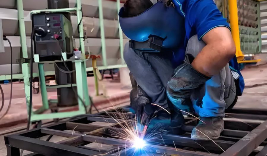
- Wearing personal protective equipment (PPE), such as helmets, gloves, and flame-resistant clothing.
- Ensuring proper ventilation in welding areas.
- Following lockout/tagout procedures for equipment maintenance.
13. Future Trends in Weld Quality Assessment
13.1 Digital Twin Technology
Digital twins—virtual models of welded components—enable real-time monitoring and predictive maintenance. By simulating weld performance under various conditions, digital twins can identify potential defects before they occur.
13.2 Additive Manufacturing Integration
As additive manufacturing (3D printing) integrates with welding, new quality assessment methods are emerging. For example, in-situ monitoring during directed energy deposition ensures defect-free builds.
13.3 Sustainability in Welding
Advances in eco-friendly welding processes, such as friction stir welding, reduce energy consumption and emissions, aligning with global sustainability goals.
14. Conclusion
Identifying a good weld requires a comprehensive, systematic approach that combines visual inspection, non-destructive and destructive testing, and adherence to industry standards. By following the ultimate checklist outlined in this article, welders, inspectors, and engineers can ensure that welds meet the highest quality standards, ensuring safety, reliability, and performance in critical applications. The integration of advanced technologies, such as automation, AI, and digital twins, promises to further enhance weld quality assessment, making it more efficient and precise. As welding continues to evolve, ongoing training, certification, and adherence to environmental and safety practices will remain essential for maintaining excellence in weld quality.
Maximize Tooling and CNC Metal Spinning Capabilities.
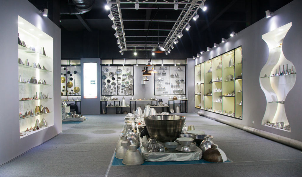
At BE-CU China Metal Spinning company, we make the most of our equipment while monitoring signs of excess wear and stress. In addition, we look into newer, modern equipment and invest in those that can support or increase our manufacturing capabilities. Our team is very mindful of our machines and tools, so we also routinely maintain them to ensure they don’t negatively impact your part’s quality and productivity.
Talk to us today about making a rapid prototype with our CNC metal spinning service. Get a direct quote by chatting with us here or request a free project review.
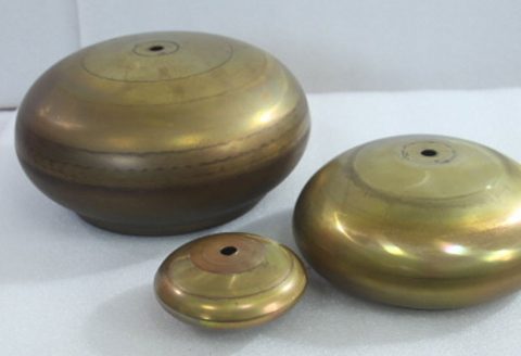
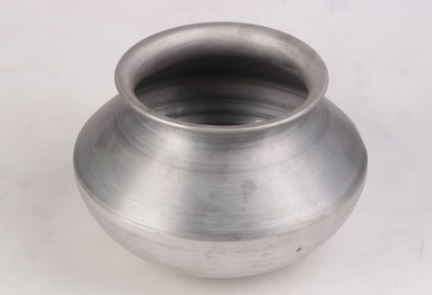
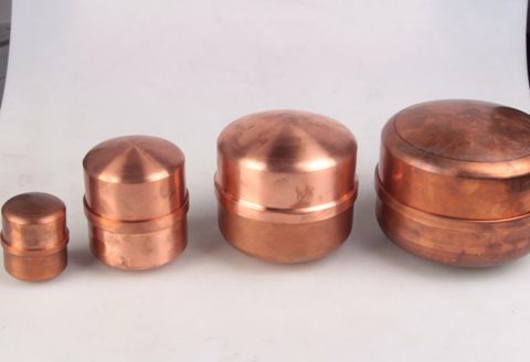
BE-CU China CNC Metal Spinning service include : CNC Metal Spinning,Metal Spinning Die,Laser Cutting, Tank Heads Spinning,Metal Hemispheres Spinning,Metal Cones Spinning,Metal Dish-Shaped Spinning,Metal Trumpet Spinning,Metal Venturi Spinning,Aluminum Spinning Products,Stainless Steel Spinning Products,Copper Spinning Products,Brass Spinning Products,Steel Spinning Product,Metal Spinnin LED Reflector,Metal Spinning Pressure Vessel,
